YouTube player

This guide will show you how to build a playful puppy robot that can be programmed with the Arduino IDE. Sample code is provided that will let you control the robot with simple hand gestures to perform tricks such as shaking hands and walking on his back legs.

The robot is relatively simple to build and is made from robot parts and accessories available in many online robot shops. You only need a couple of screwdrivers and some pliers. No soldering is required!

You can download the instruction manuals for the Quad Bot chassis and the Magician controller here.

This project works best with a LiPo battery but can be built using six NiMH AA batteries if required. When you download the sample code choose the code that suits your battery type as the balance is a little different when the robot stands on its back legs.

Project Steps

Assemble your Quad Bot chassis

A PDF of the Quad Bot instruction manual can be downloaded from the DAGU products support site. Begin by checking that all your servos are centered. When you look through the clear housing above the cable you should see a stop on the output gear. This stop should be central so that the servo can rotate 90 degrees in either direction.

Mount the foam rubber feet as shown in the instruction manual onto 4 of the 8 leg segments. All leg segments are identical so it does not matter which 4 you choose.

Mount a miniature servo on each of the 4 leg segments that you put a foot on. Make sure the servo output shaft is away from the foot as shown. These are your “Knee” servos.

Now take the 4 remaining leg segments and mount servo horns as shown. These leg segments can now be mounted on the servos as shown. The leg should be able to straighten out or fold up. If not then remount the segment.

You should now have 4 identical legs. We need to make 2 of them “Left” legs and the other 2 will be “Right” legs. The only difference is how we mount the “Hip” servo. Note which side the servo output shaft is on.

Next we need to mount the 4 round servo horns onto the Quad Bot chassis. Do not mount them as shown in the instructions. Mount them closer to the end of the mounting plate as shown in the third photo to make more room for your battery.

Mount your 4 legs. Note that the rounded end will be the back and has a hole in the center so you can mount a tail if you wish. Connect the 4 servo extension cables to the front leg servos.

Assemble the pan/tilt kit

Align your servos as shown in step 1 and assemble the kit according to the instructions. This kit was originally designed here.

Mount your compound eye with the brass spacers provided so that the wires come out at the bottom.

If possible use female-to-female jumper wires at least 150mm (6 inches) long to connect your eye to the controller. In my case I used a female-to-female connected to a male-to male-jumper wire. As the Magician controller has both male and female headers on the I/O pins it doesn’t matter too much what wires you use.

Mount the pan/tilt assembly

I used a couple of 25mm (1 inch) hex brass spacers to mount my pan/tilt assembly. The pan/tilt assembly is then fitted to the Quad Bot mounting plate using a couple of pan-head screws. If you don’t have pan-heads then use normal screws with washers.

I have mounted my assembly a reasonable way back to improve the robot’s balance and to reduce the chance of the pan and tilt servos being damaged as a result of the head hitting walls or furniture. If you change this then the robot may not be able to stand on his back legs.

Mount the battery

I have previously tried making this robot with NiMH batteries. Because of the current draw I found that AA batteries were required and that they were a bit too heavy. The robot worked OK but it could not stand on its back legs. You just can’t beat LiPo batteries for power/weight ratio.

Your battery needs to be not much bigger than 50mm x 60mm; otherwise it will restrict leg movement.

Cable-tie your battery in place with your wires coming out on the right-hand side, remembering that the curved end is the back. Make sure your battery will not obstruct the legs. Do not overtighten the cable ties. If your battery tends to slip out then use a small piece of double-sided tape between the battery and the mounting plate.

While you have the cable ties out, now is a good time to tidy up the servo cables. Make sure the servo movement is not restricted.

LiPo batteries are great but can catch fire or explode if mistreated. Do not use a battery that shows any signs of damage or swelling. Do not allow the battery voltage to fall below 6V otherwise damage can occur. Use a suitable LiPo charger and be careful not to overcharge your battery. When charging your battery keep it away from flammable liquids and objects.

If you do not have a suitable LiPo battery or do not feel comfortable using them then use 6x NiMH AA rechargeable batteries. A 2×3 battery holder will fit but the weight is greater so the robot cannot stand on its back legs.

Mount the Magician robot controller

The Magician robot controller is ideal for this project because of its low cost and that fact that it can drive both servos and DC motors without additional shields.

You can download the Magician controller instruction manual from the DAGU products support site.

Mount the controller with the analog inputs closest to the head. Note that two of the analog inputs have been converted to servo outputs to drive the pan and tilt servos.

Wiring it up!

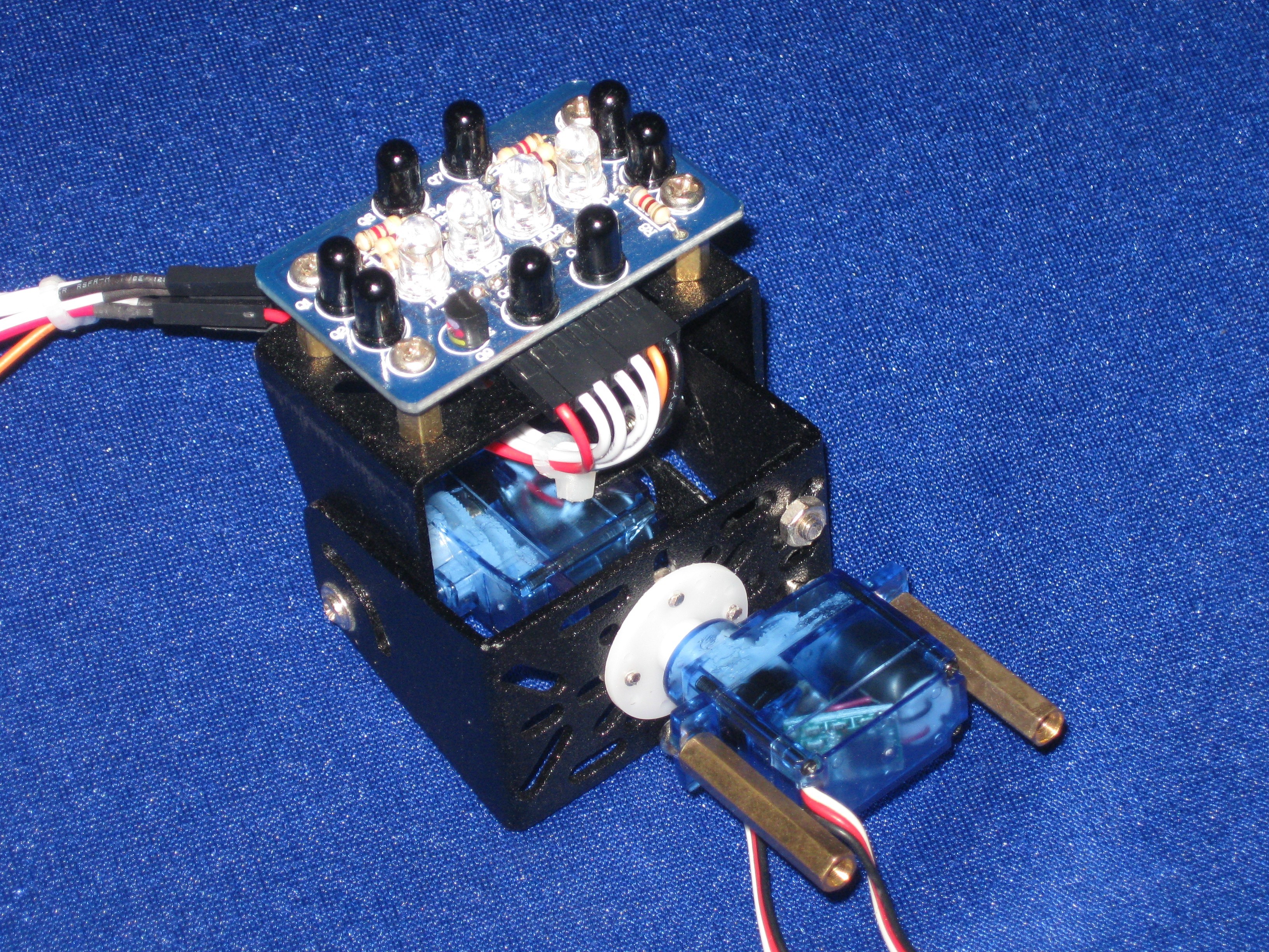
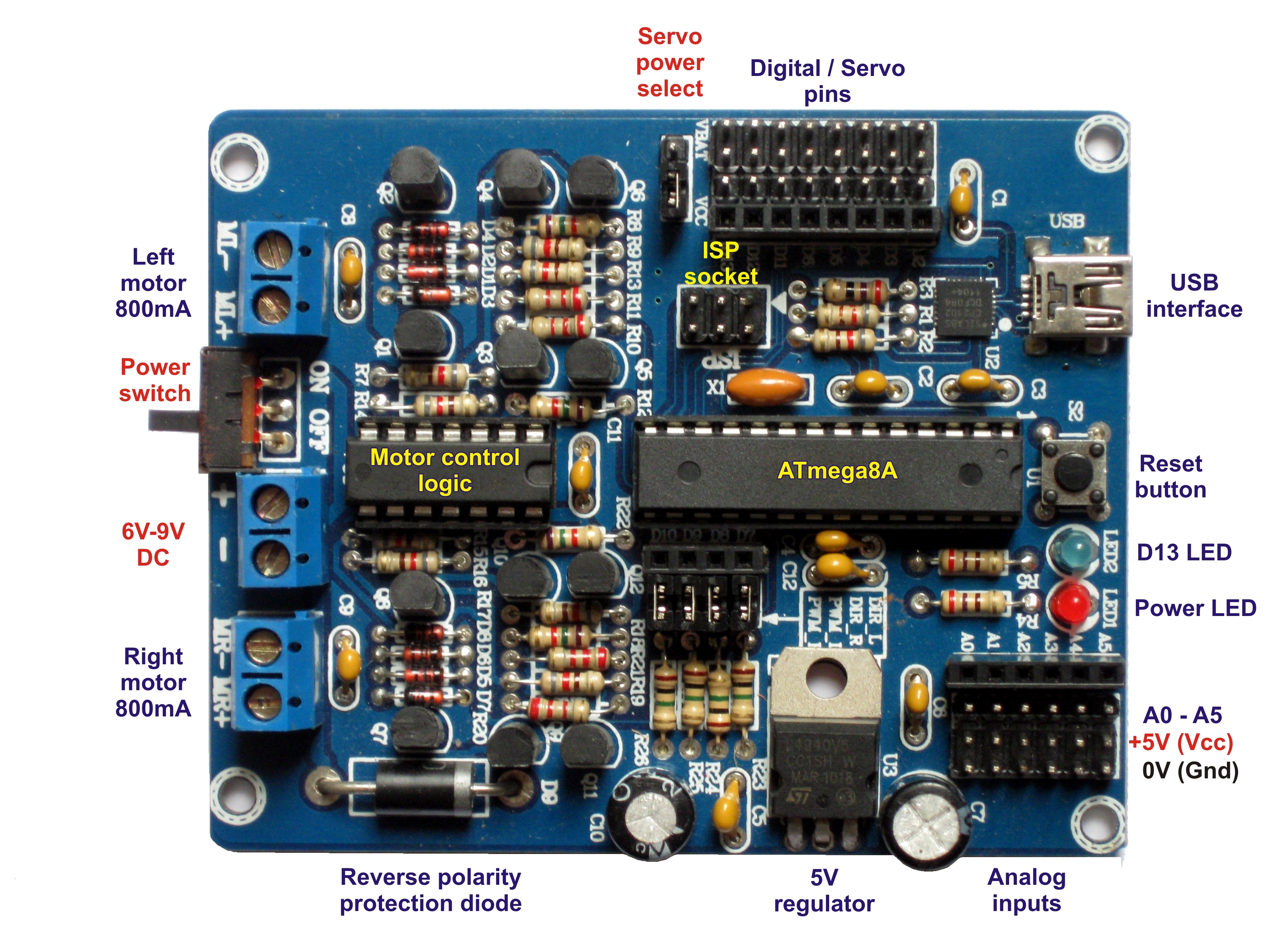
Wire the head to the analog inputs so that A0 is top, A1 is left, A2 is bottom, A3 is right, A4 is pan and A5 is tilt. Make sure the white/orange wire from the servos connects to the pin closest to the female header. The control wire for the IR LEDs connects to D8. Remove the the jumpers for D8 and D10 to isolate the right motor control circuit.

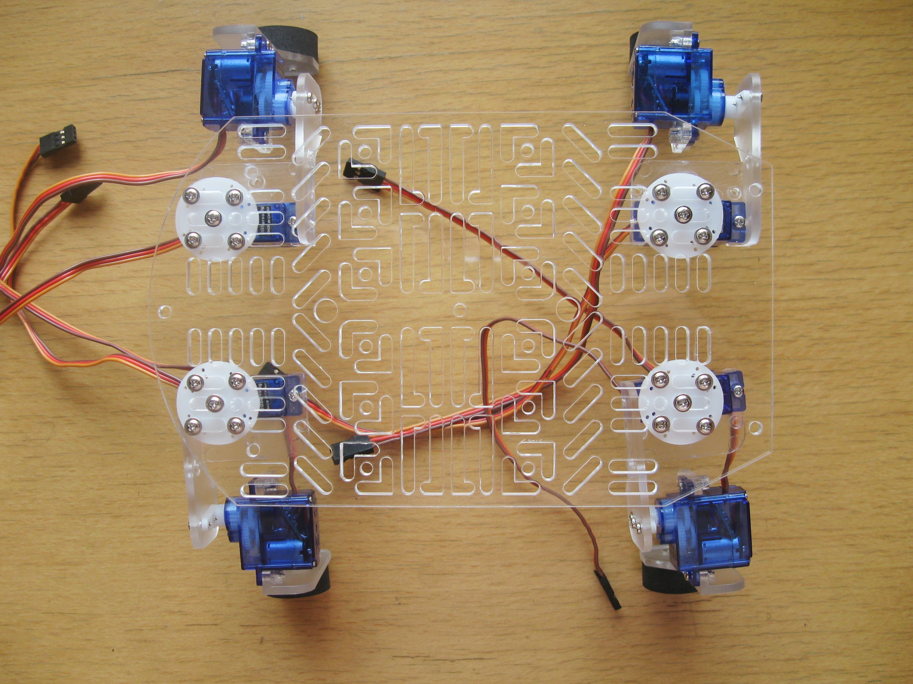
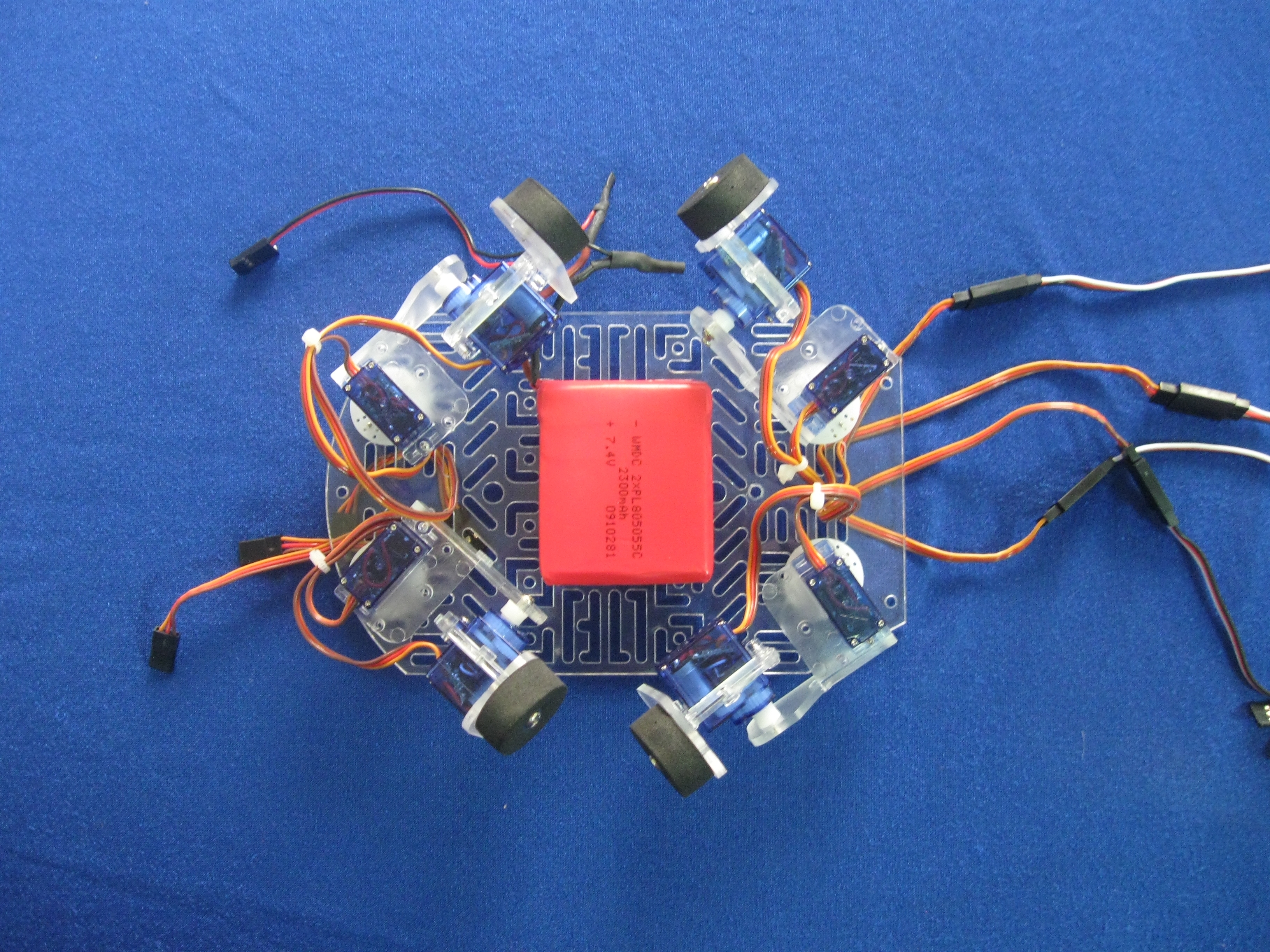
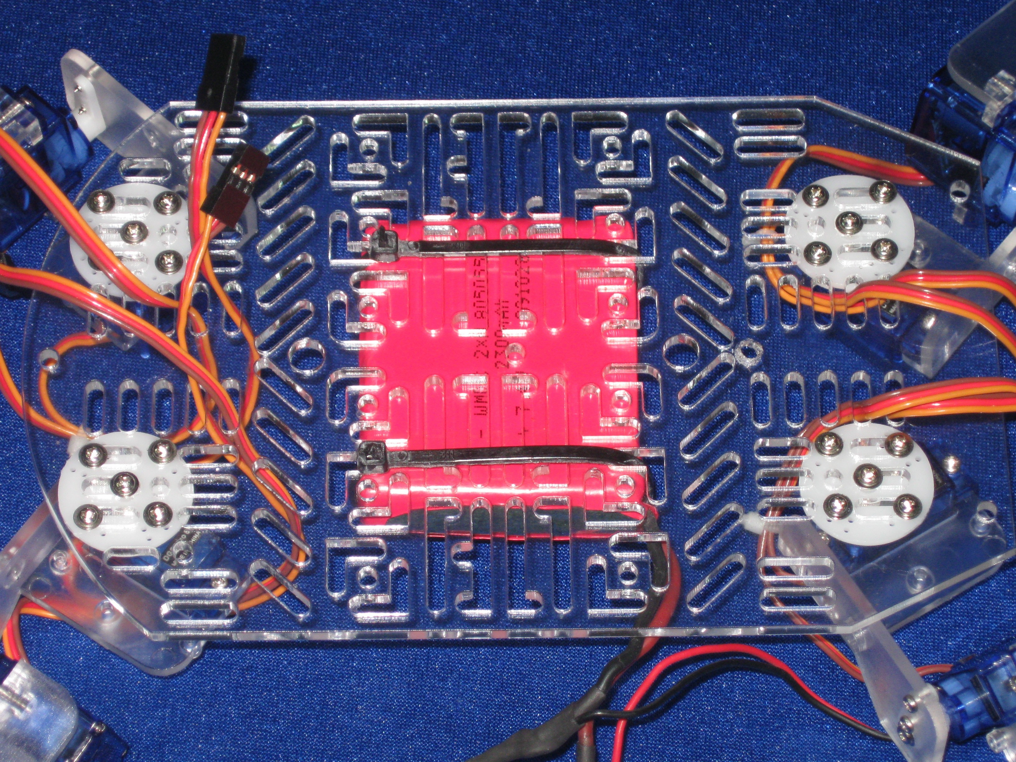
Connect your hip and knee servos next. D2 is the rear left hip, D3 is the rear left knee, D4 is the front left hip, D5 is the front left knee, D6 is the front right knee, D11 is the front right hip, D12 is the rear right knee and D13 is the rear right hip. Once again have your white/orange signal wire closest to the female header.

The pan and tilt servos are powered from the 5V regulator as they are connected to the analog pins but your legs need more power!

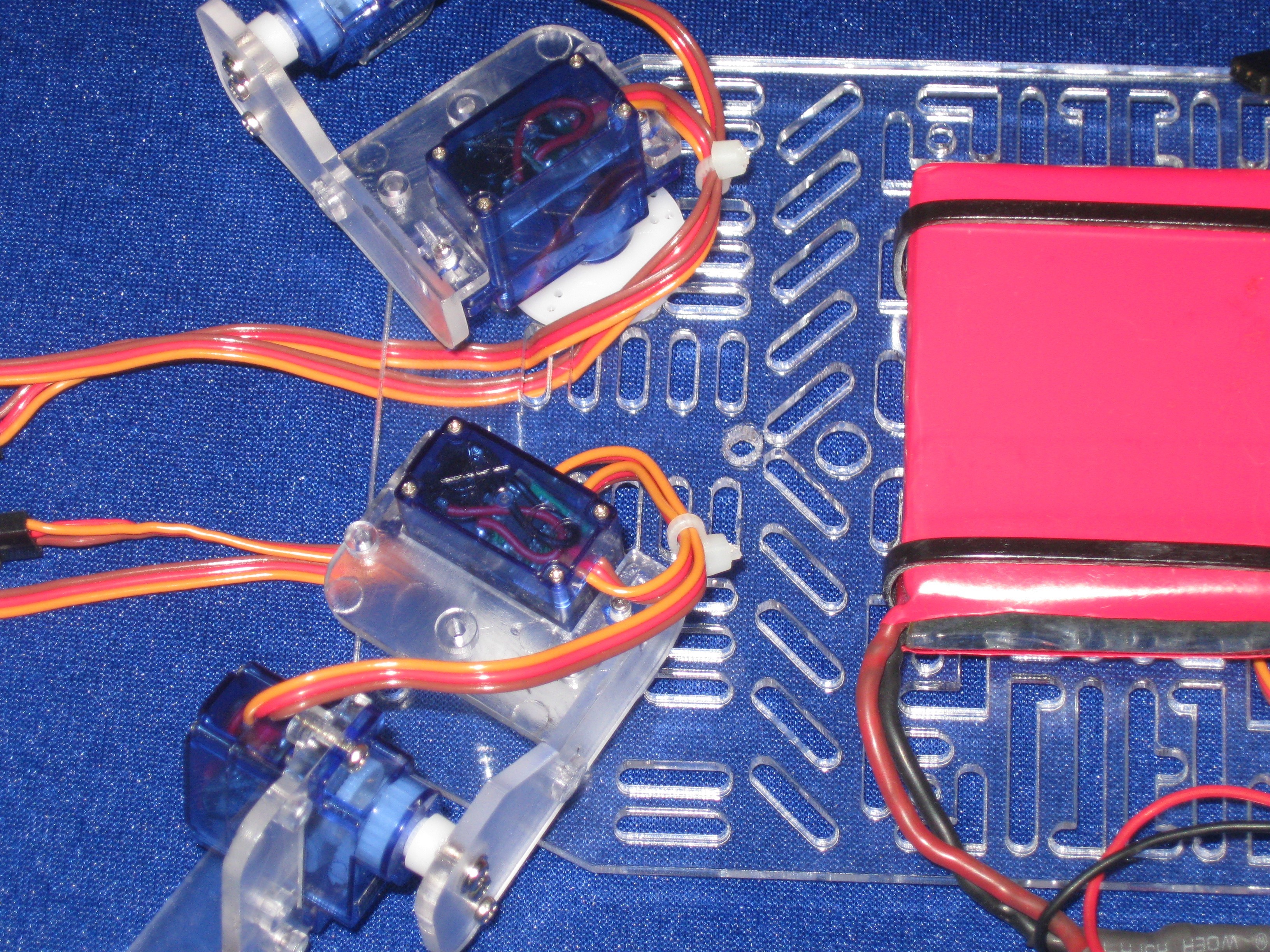
The legs can draw about 3A when doing strenuous work so they are connected to the battery by two 3A diodes (1N5400). These diodes reduce the battery voltage by about 0.7V each and the LiPo has a nominal voltage of 7.4V so the end result is that the servos get the 6V they are rated for. One of the diodes is the reverse-polarity protection diode on the controller. The second diode we fit in place of the servo power selection jumper.

Fortunately for us the legs on a 1N5400 diode are just a tiny bit thicker than a male header pin so we can use two short female-to-female jumper wires to connect our diode to the PCB without soldering. If you’re using NiMH batteries, which are heavier, then you can leave this diode out. The servos will be running at 6.6V but this is necessary for the robot to stand on its hind legs.

Admittedly, when the LiPo is fully charged (8.4V) your servos will get 7V and may get a bit hot. If you live in a warm climate and wish to extend the life of your servos then you can add a second diode in series giving you 6.3V when the battery is fully charged and 5.3V nominal. My robot works fine and the temperature is above 30°C.

Adding a tail.

This is an optional step and can be skipped if you wish.

I used a short length of spiral wrap to make a tail. I plugged one end with some hot glue and then used a self-tapping screw to fix the tail to the back of the robot. I cable-tied a small mobile phone vibrator motor to the tail that is driven by the left motor output. The sample code feeds more power to the motor as your hand gets closer.

You can make your own version of spiral wrap by feeding a drinking straw through a pencil sharpener (not the motorized kind). Another alternative is a pipe cleaner from a craft shop.

Any small motor can be used make the tail shake. Just mount a small off-center weight such as a 6mm (1/4 inch) nut to the motor shaft with some hot glue.

Loading the software

The Magician controller comes preloaded with the Arduino bootloader. If you do not have the Arduino software then it can be downloaded for free here.

The sample code can be downloaded from DAGU’s product support site. Go to the “Sample Code” page and select “Quad Bot Puppy LiPo” or “Quad Bot Puppy NiMH” depending on which batteries you are using. NiMH batteries are heavier so the balance is slightly different.

The program has descriptive comments on most lines and has seperate tabs for constants where you can adjust servo center positions and I/O pin definitions.

Before you can upload the program to the controller you must choose the correct board type: “Arduino NG or older w / ATmega8”.

If your computer does not detect the USB serial port then you can download the drivers from the DAGU product support site or from Silicon Labs.

Once the software is installed then you may need to adjust the servo center positions so that all hips are at 90 degrees to the body and that the knees are bent inward slightly. The photo at the start of these instructions show you how the robot should look after it first stands up. If you have problems with your robot then please start a forum on LMR so that I and other robot hobbyists can help you.

Controlling the robot with hand gestures.

The robot will happily run around following your hand all day but there are a few tricks he can perform.

If you do not play with the robot then after 3 seconds it will sit down. Once the robot is sitting you can bring your hand slowly within range. At this point it will follow your hand with its head. If you move your hand down towards one of its front legs slowly then it will raise its paw to shake hands. If you bring your hand between its paws then it will lie down.

Once the robot is sitting or lying down you will need to bring your hand to one side of its head to get it to stand up or above its head to make it jump up.

If you get the robot to look straight up then it will try to jump onto its back legs. Once on its back legs it will still try to follow your hand. If you can keep your hand within range then the robot will walk on its back legs.

Conclusion

Once the robot is built, install the sample software and have fun. Experiment with the program and teach your puppy new tricks.