YouTube player

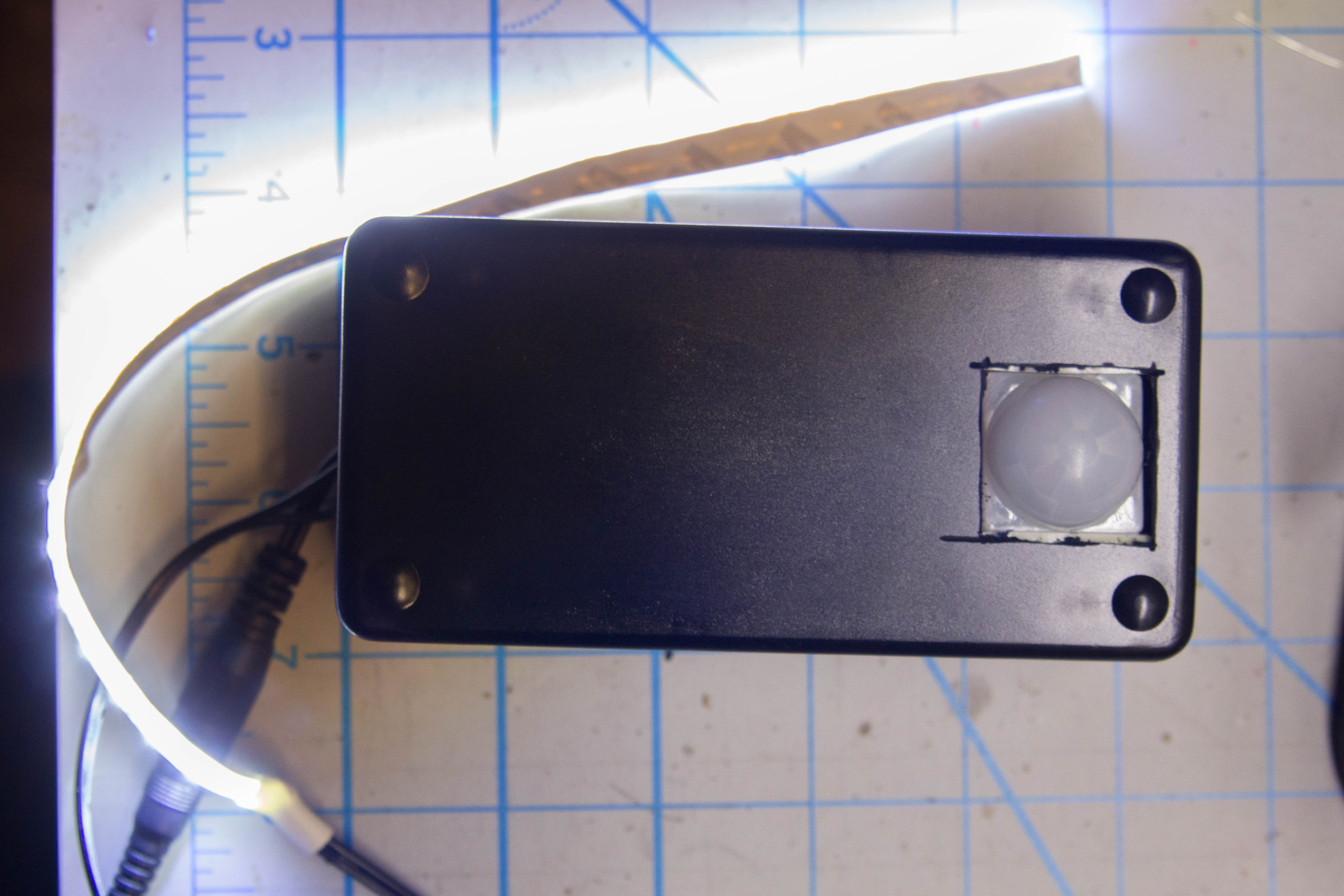
I’ve always been a fan of “presence lights” that turn on when I walk into a space. Sure, call me lazy, but there’s just something wonderful about electronics being able to anticipate my needs and look after them before I take action on my own.

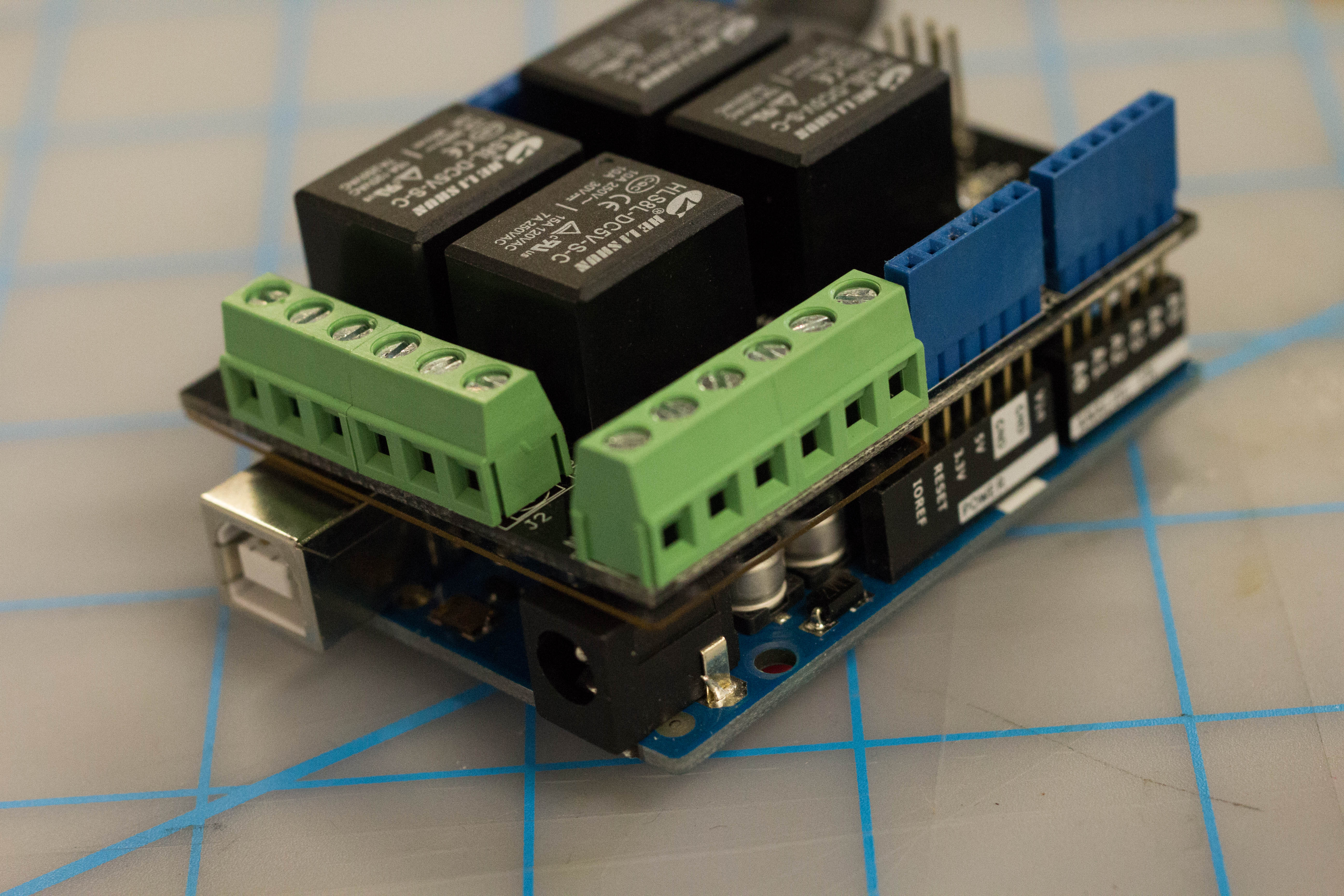
I’ve been enjoying working with these LED strip lights for a number of projects now, and controlling them with an Arduino seemed the right way to do this — even though the voltage difference presented a roadblock. I recently picked up an Arduino Relay Shield at an electronics shop fire sale, and that’s when it all came together for me.

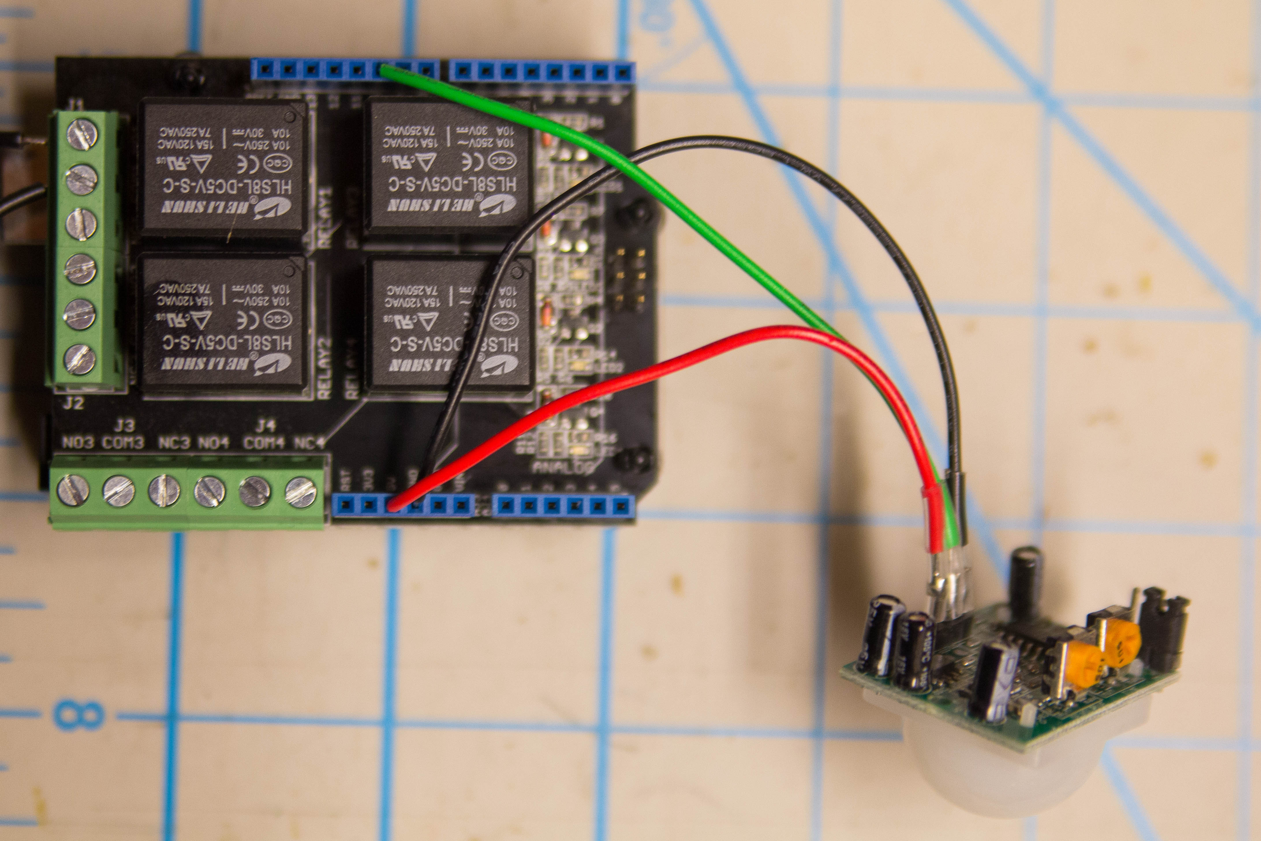
This project uses a PIR, or passive infrared sensor. These sensors make up the core of most commercial motion sensors used in security systems, but they’re also cheaply available and very adaptable into Arduino projects. The sensor works by detecting the infrared radiation emitted from humans or pets. You can tune the sensor to your needs by using two screws — one to adjust the sensitivity of the sensor, and the other to set the delay before it sends the signal to the Arduino. We’ll use the sensor to track movement and, when detected, throw the relay to activate the lights.

Project Steps

Build the LED circuit

Start by building the connecting wire for the lights.

Using a piece of hookup wire, connect the positive terminal of the LED lights to the center pin of the DC jack.

Then, solder one wire to the negative terminal of the LED strip, and another to the sleeve terminal on the DC jack.

Wire these two loose ends into the COM1 and NO1 (normally open one) terminals on the relay shield, and then tighten the terminal screws.

Connect the PIR sensor

Fit the relay shield onto the Arduino board.

Wire up the PIR sensor. If you have male-female jumper wires, you can skip out on some soldering, but either way, the connections are the same.

Wire the voltage in on the PIR to a 5V pin on the Arduino, the middle pin to digital pin 10, and the ground wire of the sensor to any of the grounding pins on the Arduino.

Upload the Arduino Sketch

Your build is functionally complete at this point, so it’s a good time to upload and test the code. Connect the Arduino to a computer and upload the TKTK LINK TO CODE TKTK code onto the board.

When you run the sketch, pop open the serial monitor, and you’ll notice that the PIR sensor takes about 45 seconds to initialize before the output begins.

Once that data begins to display on the serial monitor, wave your hand in front of the sensor to check it — even if you don’t have the lights powered, you can verify everything working by listening for the actuation of the relay.

Install in the Project Enclosure

Once the code is loaded, you’re ready to finish the installation. Mark and cut a 24×24mm square hole for the PIR sensor in the top of the enclosure, like you see here. Then drill a hole for the DC jack and another small hole to run the output wires through.

Using some thin strips of double sided foam tape, mount the PIR sensor to the inside of the enclosure. Install the DC jack and fit the wires through the other hole.

Connect the Arduino to power using a 9V battery — if the enclosure is too cramped, you can save space by soldering the battery clip wires straight to the barrel connecter terminals on the board.

Install the Lights

Supply power to the LEDs by connecting the power supply to the DC jack in the enclosure.

Check to make sure that the PIR sensor is triggering normally, and you’re all set to mount your lights.

The adhesive backing for the LED strips gives you plenty of options to mount them, and you can cut the LEDs at the specified cut points and re-solder them together in any arrangement you like.