Photos: Neil Mendoza

Projection mapping is nearly everywhere these days from advertising campaigns to huge stage shows. This isn’t really a surprise. If done well, it can immediately transform a space into something unreal.

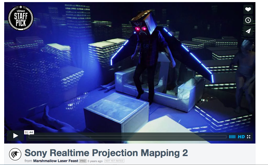
Before we begin, here are a few recent examples to whet your appetite: The Box combines projection mapping with robotics, to map moving canvases. Omicron is a permanent large scale projection mapping of a beautifully architected 65 meter dome. One Degree of Freedom is my own example of interactive projection mapping using a sensor to track the movement of the mapped object.

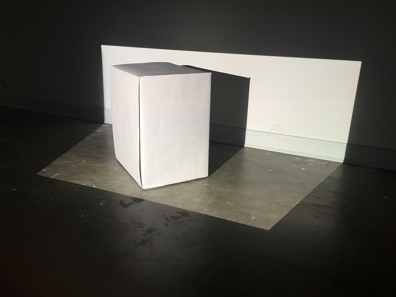
In its simplest form, projection mapping involves creating visuals that align with real world objects and then projecting them on to those objects. Normally, this process is done using computer graphics. These graphics be generated in real time, where the computer is rendering the graphics on the fly, similar to the way a computer game generates graphics. The advantage of this approach is that the visuals can be tweaked instantly (for instance, if the projection doesn’t align), it can be interactive and also generative (meaning that the graphics could be constantly changing without ever repeating).

The other approach is to pre-render a movie to project. This might be done with a software package such as Adobe After Effects. The advantage of this approach is that much more computationally intensive rendering algorithms can be used.

There are already quite a few articles out there that cover how to use various bits of software to do projection mapping. This article aims to cover some of the fundamental ideas behind projection mapping. In order to do this we are going to write our own projection mapping software from “first principles” using openFrameworks. However, the concepts presented here should be useful when approaching any type of projection mapping.

Prerequisites

Some familiarity with C++ and openFrameworks (OF) is necessary to get the most out of this article although there are example projects so, if you want, you can skip to the end of each step and compile and run the program. If you’ve never used openFrameworks before, then I’d advise you to have a look at some of the tutorials on the openFrameworks website.

Before we get started you’ll need to download OF 0.9 (available here). Once you’ve downloaded it, have a look at the IDE setup guide (linked to from this download page) for the operating system that you are using.

We will also use three OF addons: ofxGui (included with OF); ofxWarpableMesh (download here); and ofxPostProcessing (download here). Download the addons that aren’t included with OF and then unzip them to your OF addons folder.

The code examples for the article are available on my GitHub. They should be unzipped to the apps folder within OF so your folder structure will be…

YOUR_OF_FOLDER/apps/projectionmappingbasics

The name of the accompanying app for each step is given at the start of the step.

Project Steps

Modeling the Scene

OPENFRAMEWORKS APP: modellingTheScene

In this tutorial, we’re going to use a cardboard box since it is readily available and easily modeled in three dimensions. Find your favorite cardboard box. If it’s not already white, glue some paper to its sides. Measure its dimensions. We’ll use cm rather than inches because of where we live (the 21st century). However, if you really, really want to use another unit of measurement, that’s fine, as long as you keep it consistent throughout the project.

In ofApp.cpp, set BOX_DIMS to be the dimensions that you measured, where the first number is the width, the second is the height and the third is the depth …

const ofVec3f ofApp::BOX_DIMS = ofVec3f(25.f, 30.f, 20.f);

We’re going to use two ofVboMesh objects to model our box. These are declared in ofApp.h

ofVboMesh boxMesh;
ofVboMesh wireframeMesh;

The software will render wireframeMesh as a wireframe so that we can see the edges of the box while we are trying to align the projection. We don’t want to see the back edges of the wireframe so create another mesh, boxMesh, that is very slightly smaller than wireframeMesh and render it solid in order to hide the back part of the wireframe. Initialize the meshes in ofApp::setup() using the ofMesh::box() function …

wireframeMesh = ofMesh::box(BOX_DIMS.x, BOX_DIMS.y, BOX_DIMS.z, 1, 1, 1);
boxMesh = ofMesh::box(.999f * BOX_DIMS.x, .999f * BOX_DIMS.y, .999f * BOX_DIMS.z, 1, 1, 1);

Then render them in ofApp::draw()

// starts drawing the 3d scene from the point of view
// of the camera
camera.begin();

// enable depth testing so that the box mesh masks
// the wireframe at the back of the box
ofEnableDepthTest();

// draw our box mesh in black
ofSetColor(0);
boxMesh.draw();

// now draw a the wireframe
ofSetColor(255);
wireframeMesh.drawWireframe();

// disable depth testing
ofDisableDepthTest();

// finish drawing the 3d scene from the point of view
// of the projector
camera.end();

You should end up with a box of the same dimensions that you measured that you can rotate by dragging the mouse.

Setting up the Projector

Next, position the projector in a way that covers your box with light. The closer you can get the projector, the brighter and higher resolution the projection will be. Most projectors project upwards so to get full coverage the best solution may be to position your projector above the box turned upside down. Most projectors will also have an option for this in their system settings to enable you to compensate for the flip.

Modeling the Projector

OPENFRAMEWORKS APP: modellingTheProjector
ADDONS: ofxGui

The next task is to get the projection of our virtual objects to line up with the objects in the real world. There are various ways to do this. This simplest is to drag 2D shapes around in the mapping software until they match up with the object being mapped.

However, in this tutorial, we’ll create software that uses the virtual 3D scene for the mapping. There are several advantages to this. One is that if you are mapping a complex 3D scene that you already have a model of, for example a building or a 3D print, then you can map the whole thing by quickly tweaking a few parameters rather than matching every vertex. Another advantage is that, because you have a virtual 3D object, you can use all the tools in your 3D box of tricks such as lighting, shadows and depth testing to create your dream mapping.

To do the mapping in 3D we can think of a camera as working the opposite way from a projector.

A camera receives light reflected from a volume of space whereas a projector sends light out to a volume of space. In computer graphics, this volume is called a view frustum. We need our virtual camera’s view frustum to line up with our projector’s “view” frustum.

In step 1, an ofEasyCam object enabled us to rotate the object using the mouse. Now that we want to lock the virtual camera into the same position as the projector, switch the declaration to being an ofCamera in ofApp.h

ofCamera projector;

In order to get the virtual camera and the projector to align we need to set a few parameters. One of those is the field of view of the projector. This can be calculated using some basic trigonometry, the projector’s resolution and the projection size at a given distance. Those bits of data should be on your projector’s data sheet (downloadable from the manufacturer’s website). I’ve put the math you need into this spreadsheet.

For these calculations to work, the projector needs to be running at its native resolution. If the computer that you’re using has a screen connected to it (in addition to the projector), mirror the displays and make the resolution the same as the projector’s native resolution. If your screen cannot handle the projector’s native resolution, disable it in system settings.

The other parameters we need to set are the position and orientation of the projector relative to the mapped scene. Measuring these parameters precisely can be fairly time consuming, especially the angle of the projector since the projector’s “view” frustum is normally tilted upwards to enable it to project from a flat surface without being shadowed. To remedy this, measure everything approximately and then add a user interface that will allow you to tweak the parameters by eye. To create the user interface (UI), use the UI addon that comes with openFrameworks. First declare it in ofApp.h

ofxPanel gui;
ofParameter projectorPosition;
ofParameter projectorTilt;
ofParameter boxAngle;

Then set it up in ofApp::setup()

gui.setup();
gui.add(boxAngle.set("boxAngle", 0.f, -90.f, 90.f));
gui.add(projectorTilt.set("projectorTilt", 0.f, -30.f, -10.f));
gui.add(projectorPosition.set("projectorPosition",
ofVec3f(0.f, 0.f, -200.f),
ofVec3f(-10.f, 20.f, -150.f),
ofVec3f(10.f, 50.f, -100.f)));

As we don’t have access to the ofCamera variables directly, set up two callback functions in ofApp::setup() that are called whenever projectorPosition and projectorTilt are changed by the UI …

projectorPosition.addListener(this, &ofApp::projectorPositionChanged);
projectorTilt.addListener(this, &ofApp::projectorTiltChanged);

We also want the adjustments we make in the UI to be saved so in ofApp::setup() add …

gui.loadFromFile("settings.xml");

Then in ofApp::exit() add …

gui.saveToFile("settings.xml");

Now run the program, enter the data that you measured and tweak it to get the projection to line up as best you can.

Warping the Mesh

OPENFRAMEWORKS APP: tweakingTheMesh
ADDONS: ofxGui, ofxWarpableMesh

In this step, we’re going to tighten up the projection’s alignment with the scene. If we could measure everything exactly then this step wouldn’t be necessary. However, projector lens manufacture is not a perfect art and, as mentioned before, some measurements can be challenging. The way we’re going to get around this is by adding some functionality that allows us to warp the mesh. For a simple scene like ours, this is fine as the mesh contains very few vertices. For more complex scenes, it’s worth spending as much time as possible on the previous step.

To make the meshes warpable, change their types from ofVboMesh to ofxWarpableMesh in ofApp.h

ofxWarpableMesh boxMesh;
ofxWarpableMesh wireframeMesh;

ofxWarpableMesh needs some way of translating between the coordinates of your mouse click and virtual 3D space to be able to select vertices. To enable it to do this, pass ofxWarpableMesh a reference to our virtual camera in ofApp::setup()

wireframeMesh.setCamera(projector);
boxMesh.setCamera(projector);

We also need to let ofxWarpableMesh know what angle the box is rotated by. Do this by setting up a callback function in ofApp::setup() that is called whenever boxAngle changes …

boxAngle.addListener(this, &ofApp::boxAngleChanged);

Inside the callback function, create a matrix that represents the rotation and pass it to the meshes …

void ofApp::boxAngleChanged(float& boxAngle)
{
ofMatrix4x4 rotation = ofMatrix4x4::newRotationMatrix(boxAngle, ofVec3f(0.f, 1.f, 0.f));
boxMesh.setTransform(rotation);
wireframeMesh.setTransform(rotation);
}

Then allow ofxWarpableMesh to receive keyboard and mouse events …

wireframeMesh.setEventsEnabled(true);
boxMesh.setEventsEnabled(true);

Load the meshes, in ofApp::setup() if the saved files exist …

wireframeMesh.load("wireframe.ply");
boxMesh.load("box.ply");

Then save the meshes in ofApp::exit()

boxMesh.save("box.ply");
wireframeMesh.save("wireframe.ply");

Finally add in some code to highlight the vertex that we’re warping in ofApp::draw()

boxMesh.drawSelectedVertices();
wireframeMesh.drawSelectedVertices();

We’re now ready to move the mesh vertices around to our heart’s content. Select a vertex that doesn’t quite line up with the box by clicking on it with your mouse. The vertex should now be highlighted with a green sphere. Move it by using the arrow keys, left and right will move along the x axis, up and down move along the y axis or, if shift is pressed, the z axis until it aligns with the box in the real world. Repeat this with the other vertices until all the edges line up nicely.

Glowing Edges

OPENFRAMEWORKS APP: tweakingTheMesh
ADDONS: ofxGui, ofxWarpableMesh, ofxPostProcessing

One meme that seems to keep popping up in projection mapping is making the edges of objects glow. It may be a little tired by now but a few glowing lines never hurt anyone so let’s make that box glow.

To draw the outline, replace wireframe mesh with one that just consists of lines, so in ofApp.h rename wireframeMesh to outlineMesh, then in ofApp.cpp rather than calling ofMesh::box() to create our mesh, explicitly define the vertices of the box …

const ofVec3f ofApp::BOX_VERTICES[] = {
//back
ofVec3f(-.5f * BOX_DIMS.x, -.5f * BOX_DIMS.y, -.5f * BOX_DIMS.z),
ofVec3f(.5f * BOX_DIMS.x, -.5f * BOX_DIMS.y, -.5f * BOX_DIMS.z),
ofVec3f(.5f * BOX_DIMS.x, .5f * BOX_DIMS.y, -.5f * BOX_DIMS.z),
ofVec3f(-.5f * BOX_DIMS.x, .5f * BOX_DIMS.y, -.5f * BOX_DIMS.z),

// front
ofVec3f(-.5f * BOX_DIMS.x, -.5f * BOX_DIMS.y, .5f * BOX_DIMS.z),
ofVec3f(.5f * BOX_DIMS.x, -.5f * BOX_DIMS.y, .5f * BOX_DIMS.z),
ofVec3f(.5f * BOX_DIMS.x, .5f * BOX_DIMS.y, .5f * BOX_DIMS.z),
ofVec3f(-.5f * BOX_DIMS.x, .5f * BOX_DIMS.y, .5f * BOX_DIMS.z)
};

Then add them to the mesh …

// create an outline of a box using a mesh in OF_PRIMITIVE_LINES mode
// so that every two vertices represents a line
outlineMesh.setMode(OF_PRIMITIVE_LINES);

// add in all the vertices to the mesh
for (unsigned i = 0; i < NUM_BOX_VERTICES; ++i)
{
outlineMesh.addVertex(BOX_VERTICES[i]);
}

// rather than adding each vertex multiple times, we add
// indices that point to where the appropriate vertices
// are for each line in the outline
for (unsigned i = 0; i < NUM_OUTLINE_INDICES; ++i)
{
outlineMesh.addIndex(OUTLINE_INDICES[i]);
}

Now that we’ve drawn the outline, we need to make it glow. To do this, use ofxPostProcessing. First declare it in ofApp.h

ofxPostProcessing outlineEffects;

Then, initialize it and add a glow pass, BloomPass, and an anti-aliasing pass, FxaaPass

outlineEffects.init();
outlineEffects.createPass();

Now render the whole scene with the effects applied to it be calling this before rendering …

// look at the scene from the perspective of the projector
// when using ofxPostProcessing with a camera object we do this
// by passing the camera to the ofxPostProcessing::begin()
// function as an argument
outlineEffects.begin(projector);

Then this after rendering …

// finish drawing the scene from the perspective of the projector
outlineEffects.end();

You should now have a box with magically glowing edges.

Laser Cats

OPENFRAMEWORKS APP: tweakingTheMesh
ADDONS: ofxGui, ofxWarpableMesh, ofxPostProcessing

No self-respecting tutorial is complete without some audio reactive laser cats, so let’s add some. We’ll make a simple audio visualizer using something called a fast fourier transform (FFT) that splits a waveform into much simpler constituent waveforms. We then use the amplitude of these building block waveforms as an indicator of the levels of the different frequencies that make up the whole sound, similar to a graphical equalizer. When you play a sound using ofSoundPlayer in openFrameworks, you can get the FFT by simply calling ofSoundGetSpectrum().

First declare all the variables that we need in ofApp.h, the sound player …

ofSoundPlayer soundPlayer;

The variables that will hold the data about different frequencies in the audio file …

float smoothedFft[NUM_FFT_BANDS];
float maxFft[NUM_FFT_BANDS];
float normalisedFft[NUM_FFT_BANDS];

A frame buffer object to render our visualizer into that will be used to texture the box …

ofFbo eqFbo;

Last but not least an image object for our cat …

ofImage catImage;

In ofApp::setup(), load the sound and set some sound player settings …

soundPlayer.load("Quirky Dog.mp3");
soundPlayer.setLoop(OF_LOOP_NORMAL);
soundPlayer.play();

Then load the cat image …

catImage.load("cat.png");

Then set up a frame buffer. Setting the textureTarget to be GL_TEXTURE_2D means that we can use the texture coordinates that are generated by ofMesh::box()

ofFbo::Settings s;
s.width = 1024;
s.height = 1024;
s.textureTarget = GL_TEXTURE_2D;
eqFbo.allocate(s);

Then zero all the array variables that hold the frequency band data …

memset(smoothedFft, 0, sizeof(float) * NUM_FFT_BANDS);
memset(maxFft, 0, sizeof(float) * NUM_FFT_BANDS);
memset(normalisedFft, 0, sizeof(float) * NUM_FFT_BANDS);

Update the frequency band data every frame in ofApp::update()

// get the fft
float* spectrum = ofSoundGetSpectrum(NUM_FFT_BANDS);
for (int i = 0; i < NUM_FFT_BANDS; ++i)
{
// let the smoothed value sink to zero:
smoothedFft[i] *= 0.96f;

// then let the smoothed fft value be the maximum
// of the previous falling value or the new value
// so each will rise immediately and then fall smoothly
smoothedFft[i] = max(spectrum[i], smoothedFft[i]);

// in maxFft we hold the maximum value for this
// frequency band so far
maxFft[i] = max(spectrum[i], maxFft[i]);

// using maxFft, we then get a normalised value
//(a value between 0 and 1) and use this to draw the eq
if (maxFft[i] != 0.f) normalisedFft[i] = ofMap(smoothedFft[i], 0.f, maxFft[i], 0.f, 1.f);
}

Draw then eq into a frame buffer in ofApp::draw()

// begin drawing the eq into the frame buffer
eqFbo.begin();

// clear the frame buffer to brightness 10 (dark grey)
// and alpha 255 (opaque)
ofClear(10, 255);

// calculate how wide each bar of the eq needs to be
const float barWidth = eqFbo.getWidth() / NUM_FFT_BANDS;

// make the same number of vertical as horizontal divisions
const float barHeight = eqFbo.getHeight() / NUM_FFT_BANDS;

// loop through all of the bands of the FFT
for (unsigned i = 0; i < NUM_FFT_BANDS; ++i)
{
// cycle through the rainbow for the bars
ofSetColor(ofFloatColor::fromHsb(i / (float)(NUM_FFT_BANDS - 1), 1.f, 1.f));

// work out how many cats are in this column
unsigned numCatsInColumn = ROUND(normalisedFft[i] * NUM_FFT_BANDS);

for (unsigned j = 0; j < numCatsInColumn; ++j)
{
// draw the cat image at the appropriate place at 0.7 times
// the size of a division to leave a margin on each
// side of 0.15 times the size of a division
catImage.draw(barWidth * (i + .15f), barHeight * (j + .85f), barWidth * .7f, -barHeight * .7f);
}
}

// end drawing to the frame buffer
eqFbo.end();

Use the visualiser texture from the frame buffer to texture the box …

eqFbo.getTexture().bind();
boxMesh.draw();
eqFbo.getTexture().unbind();

Going Farther

Writing your own software means you’re not bound by any workflow and you can easily integrate external hardware, for example using sensors or motors, and software libraries. There are lots of amazing OF addons at ofxaddons.com, for example, ofxProjectorBlend to edge blend multiple projectors or ofxMtlMapping2D, a 2D mapping addon, could both come in very handy for projection mapping. If you decide that writing software isn’t for you, there are plenty of great tools on the market, for instance, MadMapper and Touch Designer.

Your imagination is the limit when creating scenes to map. If you decide to design a scene with a computer that is comprised of laser cut or CNC milled parts then you can instantly start mapping even complex scenes, because you already have a 3D model of them.

Another thing that can be interesting is giving the illusion of the scene itself changing and moving. Here’s a great example from Marshmallow Laser Feast. These kind of mappings work really well for projection mappings that are designed to end up as movies. However, due to the fact that they are perspective tricks and rely on the viewer having a fixed viewing angle they normally need to be more subtle for live mappings and have the audience as confined to one viewing angle.

Now that we’ve covered some of the basics ideas behind projection mapping, you just need to work out where you want to go with it.