This project guide explains how to build an operating railroad grade crossing signal controller (GCSC) for controlling a simulated railroad crossing signal that has working flashing lamps and striking bell. Just like the real thing!

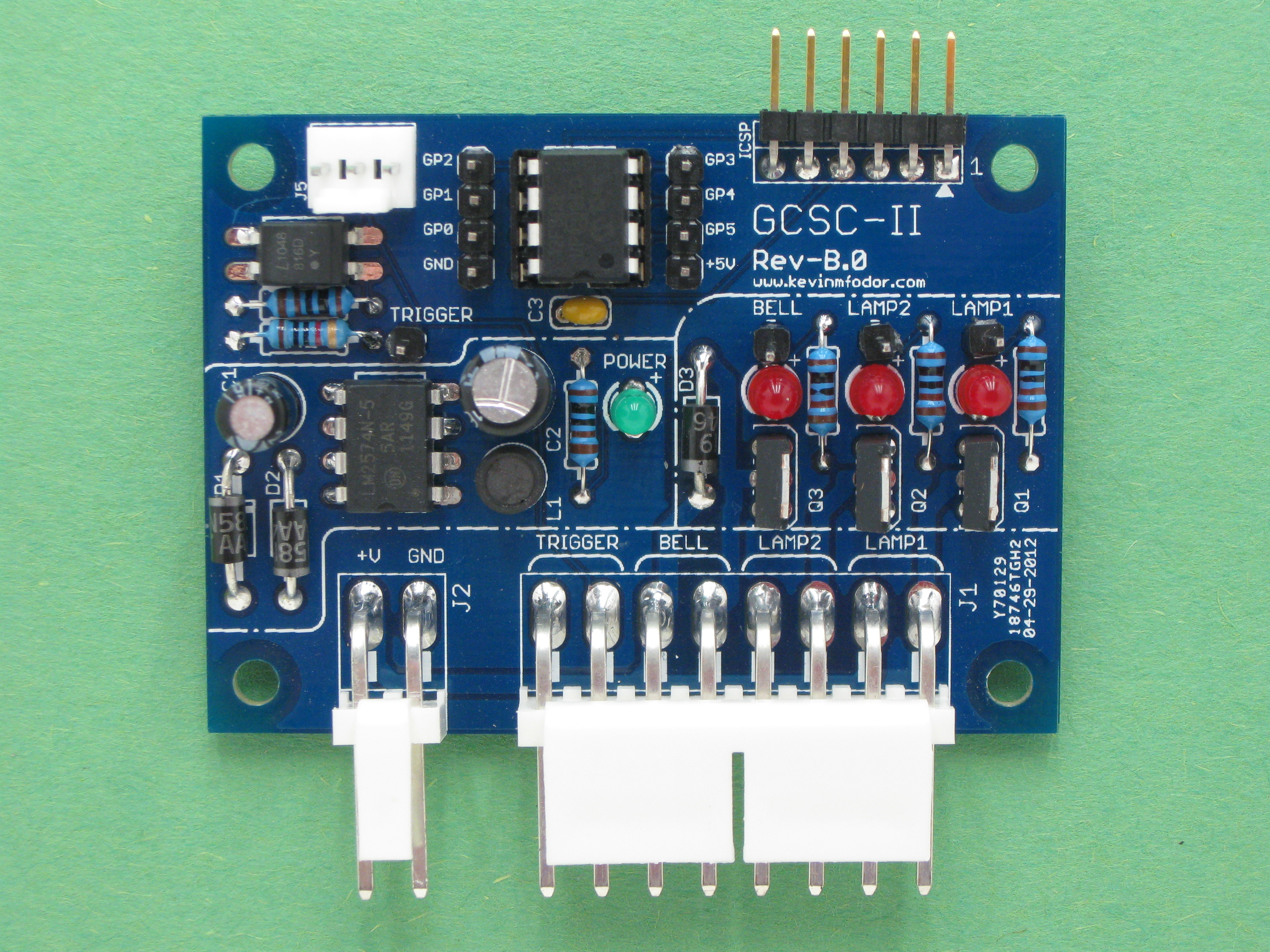
This board was also designed with hacking in mind. Due to the on-board 5 VDC power supply and extensive breakout headers and detailed silkscreening it also makes an excellent Microchip PIC12 development board. The I/O pins used for the GCSC-II implementation can be detached though small cut-trace pads on the back of the board so that you can route the micro’s I/O pins to anywhere you like. Separately the opto-isolated input and 3 high-power outputs can be re-purposed for many other projects and experiments. You can even try connecting them to your own bread board for off-board development.

All of the design and documentation for this project is maintained on a GoogleCode project site which you can find at this link: http://code.google.com/p/gcsc-ii/

There you will find the gerbers, complete parts lists and detailed design documentation for this board. Also feel free to contribute further on that site.

Along with my Blog post, this video shows one example of what can be done with this controller.

I hope you enjoy building and hacking this board as much as I did designing it. If you have done something with it and found it helpful, drop me a line. I would love to hear about it.

Project Steps

Get familiar with the blank PCB

This is a double-sided through-hole PCB with full silkscreen detail of all parts, placement and sub-system identification.

We will proceed with the smallest profile components first and work our way up to the larger components. Doing it this way allows us to get easy access to all the components while soldering them to the board.

Chuck up your PCB into a suitable vise and we can get started.

Place 10k resistor

Bend the leads of the 10k resistor and insert it into the PCB location marked R2 and solder in place.

Polarity is not important.

Place five 1k resistors

Bend the leads of five1k resistors and insert them into the PCB locations marked R3, R1, R6, R5, R4 and solder in place.

Again, polarity is not important.

Place one 0.1μF capactior

Place one 0.1μF capactior into the PCB location marked C3. This is the PIC12 microcontroller decoupling capacitor. Solder in place.

Note this is a ceramic capacitor without polarity so any direction is fine.

Place three 1N5819 diodes

Bend the leads of three 1N5819 diodes and insert them into the PCB locations marked D1, D2, and D3 and solder in place.

Be sure to observe proper orientation by making sure the line and point on the diode is the same orientation as on the PCB. D1 should be up, D2 should be down and D3 should be down as well.

Place the LM2574 voltage regulator

Place the LM2574 voltage regulator (8-pin DIP) into the PCB location IC1 and solder in place.

Be sure to observe proper orientation as the notch (pin 1) needs to be pointing down and aligned as marked on the silkscreen.

Note: You may also choose to use an 8-pin DIP socket instead at this point and replace the chip later. For instance you may want to use a 3.3V version of the regulator instead.

Place the 680μH inductor

Place one 680μH inductor into PCB location L1 and solder in place.

Note this is a simple inductor without polarity so any direction is fine.

Place one 22μF electrolytic capacitor

Place one 22μF electrolytic capacitor into PCB location C1 and solder in place.

Be sure to observe proper polarity by lining up the lead marked “-” with the right hole (the one without the “+”).

Place one 220 μF electrolytic capacitor

Place one 220 μF electrolytic capacitor into PCB location C2 and solder in place.

Be sure to observe proper polarity by lining up the lead marked “-” with the right hole (the one without the “+”).

Place one 3mm green LED

Place one 3mm green LED into location POWER and solder in place.

Observe proper polarity. The long lead (ANODE) should go into the hole marked with a “+”.

Place the optoisolator

Place the optoisolator into location IC2 and solder in place.

Again, be sure to observe proper orientation as the “dot” (pin 1) must be in alignment with what is on the PCB silkscreen. It should be pointing down next to the resistor R3.

Place three 3mm red LEDs

Place three 3mm red LEDs into locations LED2, LED3 and LED4 and solder in place.

Note these are not marked on the silkscreen but they align next to the row of 1k resistors next to Q3, Q2 and Q1.

Observe proper polarity. The long lead (ANODE) should go into the hole marked with a “+”.

Insert three power MOSFETs

Insert three power MOSFETs into locations Q1, Q2 and Q3 and solder in place.

These are static-sensitive devices; use ESD precautions.

Be careful to observe proper orientation with these devices. The metal tab should be facing to the right as on the PCB silkscreen.

Insert the PIC12F508 microcontroller

Insert the PIC12F508 microcontroller into location IC3 and solder in place.

Be sure to observe proper orientation. Notice pin 1 needs to be pointing down and aligned as marked on the silkscreen.

Note: You may decide to solder in an 8-pin DIP socket to accept the microcontroller. DIP sockets allow the easy removal of an IC from the PCB without desoldering. This is typically done during prototyping and experimentation.

You can reprogram the microcontroller in circuit using the ICSP header, but depending on how abusive your experimentation is you may want to replace it from time to time.

Also at this time you may also want to insert the optional small 3-pin molex connector at location J5.

The external connector brings out the regulated +5VDC from the power supply, a ground signal and the trigger input signal. This header is handy for instance if you want the controller to be externally triggered; say, be a remote control as described in this project: Got Wireless? Modify a Simple 12VDC Wireless Remote Control for 5VDC Operation.

Insert the 8-pin and 2-pin male Molex connectors

Insert the 8-pin and 2-pin male Molex connectors into locations J1 and J2 respectively and solder in place.

Secure these connectors in place with small clamps. Align the connectors so they are straight and flush with the PCB.

Start by soldering one pin at each end first, just to tack it into place. Then when satisifed solder the other pins.

Go back and re-flow your solder joints, adding extra solder as needed.

At this point the controller is complete, although you may want to continue to the next step to add optional breakout headers and connectors which make this board even more useful.

Optional - Insert the break-out headers.

The preceding steps will get you to the point of a fully operational board, but you may want to consider some extra break-out headers to facilitate hacking this board. If not you can also skip this step.

These 0.10″ pitch headers are handy to have if you plan on hacking this board. They bring out all of the microcontroller pins, and input and output connections to peripherals, as well as provide a 6-pin ICSP in-circuit programming port.

Insert the right-angle 0.10″ pitch header into the ICSP header location. Optional for operation of the circuit, but is required to program the microcontroller in-circuit. I recommend including it as it is quite helpful to making quick code changes and trying them out.

Insert four straight single 0.10″ header pins into the PCB to fascilitate hacking. Place these pins into the connection points for the input signals (trigger) and output signals (lamps and bell). These can also be helpful when hacking this board to do other things.

The second photo shows the locations of the cut-trace disconnects which allow you to disconnect the peripherals from the microcontroller’s I/O pins. Using the breakout headers these devices can be reconnected to any other pin.

Finally install the pair of 4-pin 0.10″ pitch headers for the microcontroller. These header pins are breakout pins which provide access to all 8 microcontroller pins.

Inspect your work

Take a look at the completed board.

Do all solder connections look smooth and shiny?

Are there any cold-soldered joints?

Did any through-hole part leads not get soldered?

Are all components snugly soldered to the board, allowing little movement?

Does it look basically like the completed photo?

Program the Microcontroller

If you are not able to obtain a pre-programmed part, you will need to program your microcontroller at least at first with the provided code so you can test it.

For this you will need to use a PIC3Kit Programmer / Debugger and the MPLAB X IDE available from Microchip.

If you do not have a programmer but need a device programmed, contact me via this site and I’ll try to help you out.

Test

To test the controller, it is easiest to connect a 9V battery (or similar) to the power connector J1. The PCB is reverse-power polarity protected, but be careful.

Note: a 9V battery is sufficient for running the controller like this. Since we are not driving any large loads via the MOSFETs (lamps, etc) a 9V battery has plenty of power to run just the controller.

Connect the battery to the power terminals

Trigger the system by touching the TRIGGER pin to GROUND.

The LEDs should begin to flash. The LAMP LEDs should flash approximately every 2/3 seconds while the BELL LED will pulse every 2/3 seconds.

You can short the trigger again and the system should shut off.

Click here for a video of a working controller demonstration: Controller Testing Video

Use

Now you’re ready to use your controller either as intended (A Railroad Grade Crossing Signal Controller) or as a PIC12 development kit for your own projects.

Conclusion

The embedded controller described here is intended to primarily be used as a controller for a railroad signal crossing. However, because of the addition of breakout headers, an ICSP connector and on-board step-down voltage regulator, it can also be used as a flexible development platform that can accommodate any compatible Microchip 8-pin PIC microcontrollers. This makes this board an excellent launching point for many other projects as well.