raspberry-pi-week_banner-1

YouTube player

When I first saw that the Raspberry Pi had an on-board connection for a camera, I knew what I wanted to build. It would be a battery powered traditional “point and shoot” camera complete with shutter button and a screen. It would run as a PyGame app and be able to act as a server so that I could access the photos over Wifi once they are taken.

Project Steps

STEP 1: SETUP THE RASPBERRY PI

To do this project I am going to assume you have already installed the latest version of the Raspbian OS, and know to update and upgrade the OS in LXTerminal using these commands:

sudo apt-get update
sudo apt-get upgrade

Once you do that you will see the choice to enable the camera option when you run the configuration options by executing:

sudo raspi-config

Look for the “Camera Enable/Disable” option.

After enabling the camera, plug it in and reboot the Pi. You’ll also need to install a GPIO library so that you can use the button you are going to make. The best GPIO library out there is RPi-GPIO. Here are the commands to install it:

sudo apt-get install python-dev
This installs the latest Python Development toolkit.

sudo apt-get install python-rpi.gpio
This installs the GPIO library.

For more details on installing the library, Adafruit has a great walk through.

STEP 2: CREATE AND CONNECT SHUTTER BUTTON

The connection to the button is done with a perfboard from RadioShack. I like to use the ones with the square pads. It’s basically using the schematic from this Adafruit tutorial on using buttons with the Pi. It has a pullup resistor and a GPIO pin for each button you need. I just cut the ribbon cable from Adafruit to make the attachment to the Raspberry Pi. I only have one button wired in, but you could do more or even make LED indicator lights using the GPIO pins.

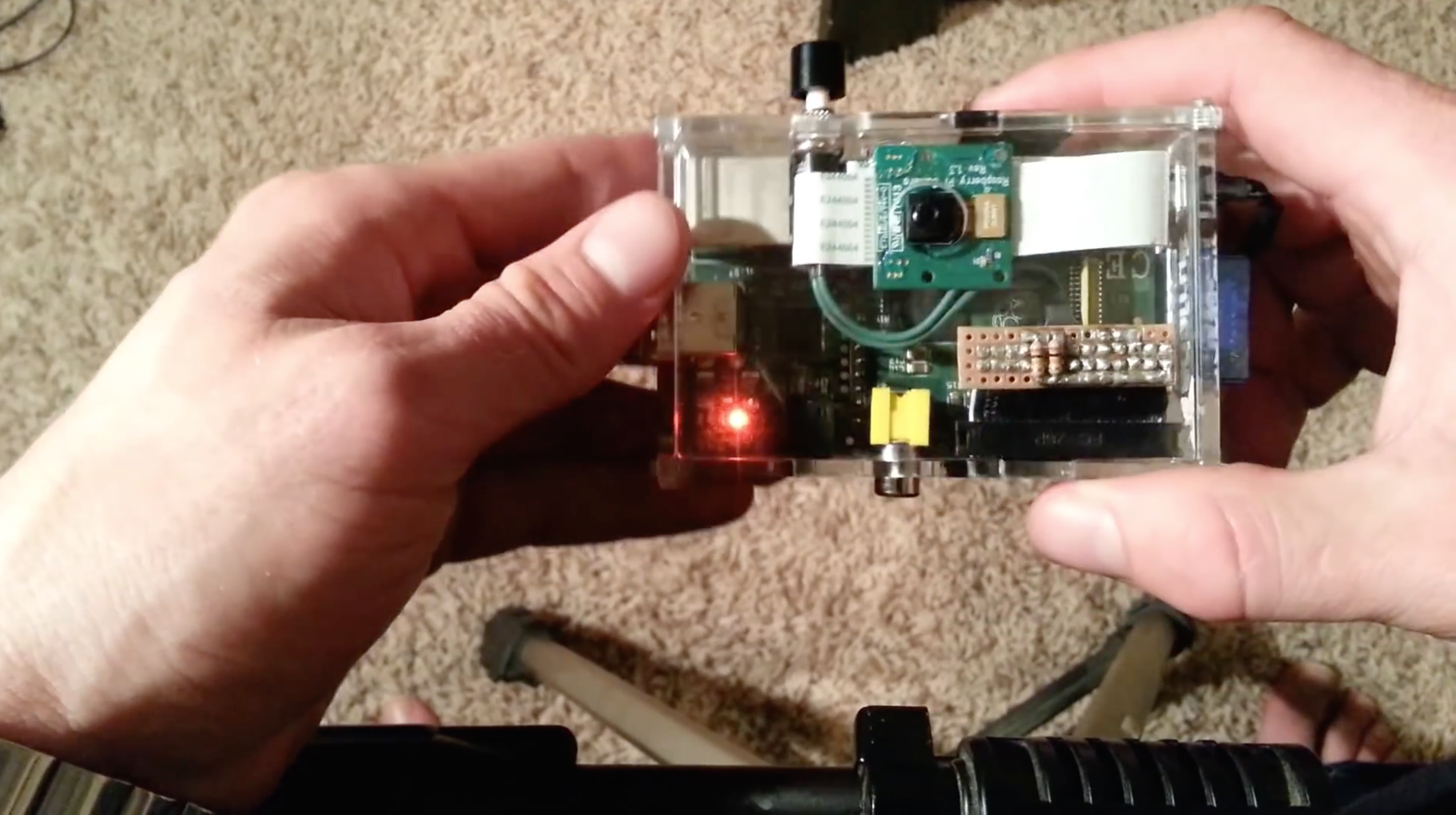
Button Shield using GPIO and Ribbon Cable

I wired in all the pins from the ribbon cable to the perfboard even though in this case I am only using a few. This was because in the future I may want to add additional buttons or use other pins. This setup means that the project can grow and I wouldn’t have to start from scratch.

NOTE: You can see that I actually have 2 pull-up resistors wired to pins 23 and 24, but I am only using GPIO pin 24 right now but pin 23 is ready for an additional button as is. I was thinking of adding the second button for taking a video but have not yet had a chance to add that feature.

Within Python, you can test to see if the button is pressed like this:

if(GPIO.input(24)==False):

This line of code looks to see if the GPIO pin 24 is currently grounded (i.e. pressed), The pull-up resistor prevents this pin from appearing grounded unless the button has been pressed.

STEP 3: CREATE THE MINI USB CABLE

The final piece was making the ultra tiny USB cable using a slice from normal sized cable and some careful soldering and glue gun usage. This way it locks in nicely and the Enercell battery lasts about 3.5 hours.

usb-cable

The USB cable can be easily made by cutting and shortenting any USB micro cable or you can make your own cable with these MicroUSB and USB A plug connector shells. If you do use these parts, make sure that the wire is thick enough to carry the current needed to power the Raspberry Pi (my first attempt failed because I was using very small ribbon cable).

STEP 4: CONNECT SCREEN

I got the screen shown above from Adafruit Industries as well. It connects to the Raspberry Pi using the RCA jack (yellow). The screen needed 6V to run, and the RPi only outputs 5V. I solved the minor voltage difference with what is called a “buck booster” I found on Ebay (circuit on left in red). It can convert the 5V output on the Raspberry Pi to 6V.

STEP 5: SETUP AND RUN CAMERA.PY

The Python file is a PyGame app that loops waiting for a button press. The code is available here. It needs to be running in order for the camera to fire, so you may need to have your RPi boot right into it. That way it the camera is ready to go every time it’s turned on.

To do that I added a single line of code to the LXDE autostart file. I chose this file instead of a few other options because I wanted it to boot into LXDE and run the application in a terminal window from there so that I could see the button presses logging on the desktop. The file I edited is located at

/etc/xdg/lxsession/LXDE/autostart

and the additional command I placed at the end of the autostart file was this:

@lxterminal -e "sudo python /home/pi/camera/camera.py

This basically starts an LXTerminal window and asks it to execute the command that starts the camera.py application.

TAKING IT FURTHER

You can also install and FTP server to access the images from your computer over the Wifi connection.

Here are a few more photos of the finished product:

If you want to see the kinds of photos that can be taken on the Raspberry Pi Point & Shoot camera, I put and album up showing a set of pictures I captured after making the first version of it. (Ignore the first picture, that was the older prototype.)

To learn about Raspberry Pi and photography, check out this tutorial.