YouTube player

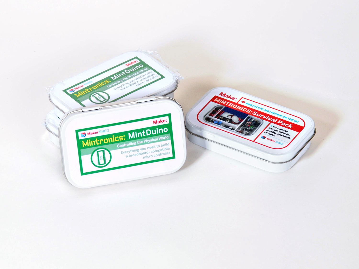
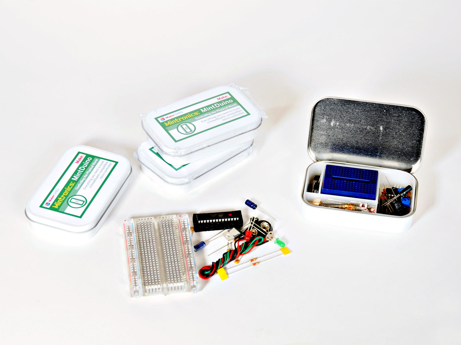
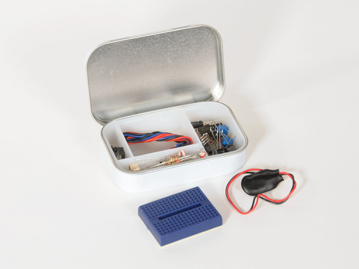
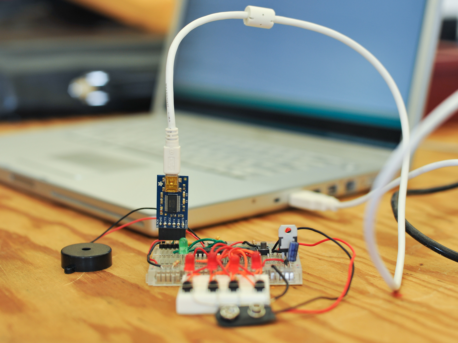
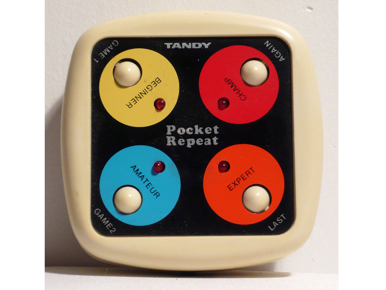
In this project, we’ll turn a MAKE MintDuino microcontroller and a Mintronics Survival Pack into a replica of retro electronic memory games like Simon and the Tandy Pocket Repeat game sold by RadioShack in the 1980s.

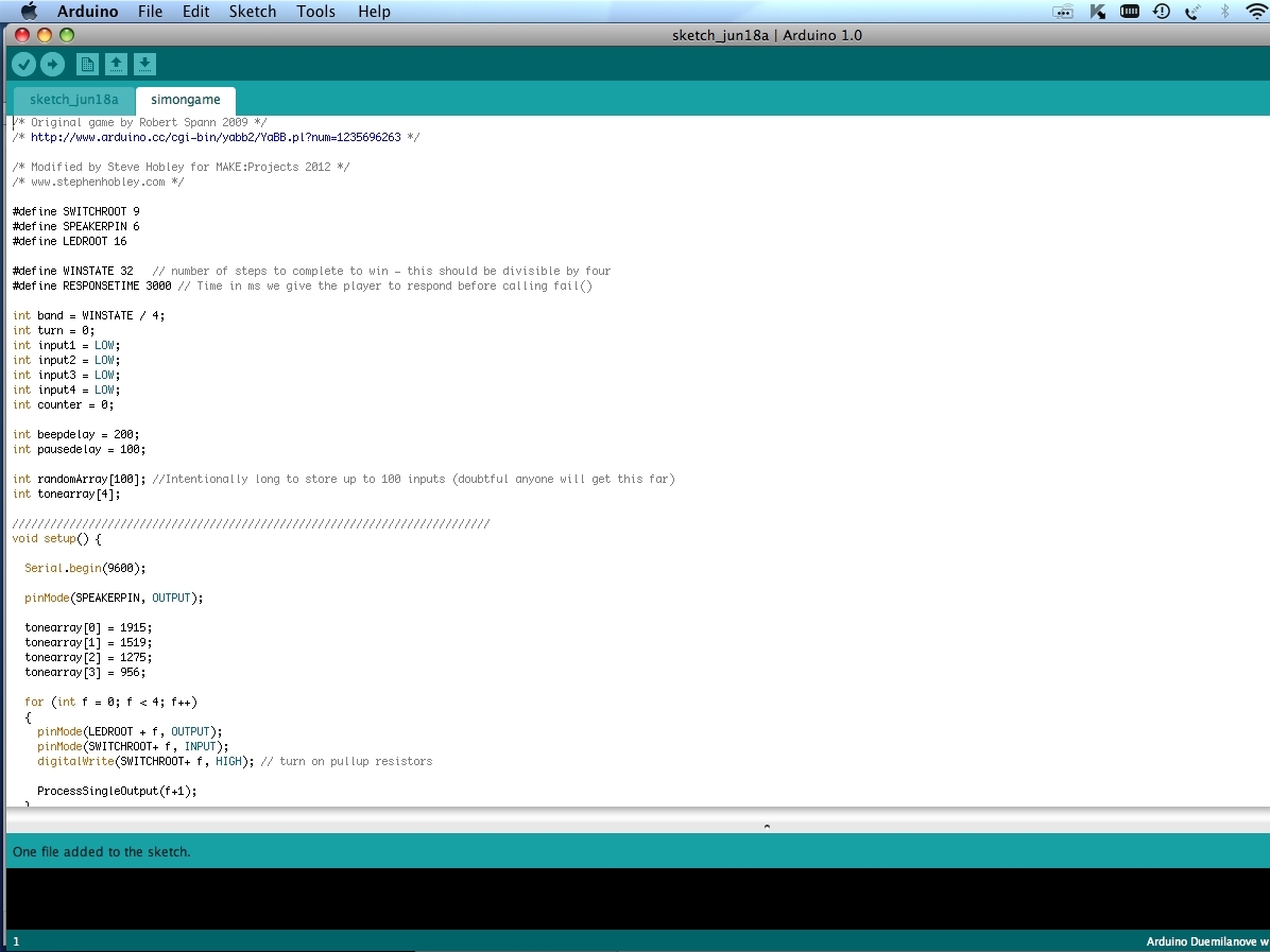
It’s amazing how fun and addictive this simple game is, and it’s a great way to learn about integrated circuits and programming. The code is very straightforward, and it’s commented to explain how each part works, so you can customize your game by experimenting with the different parameters and values in the code.

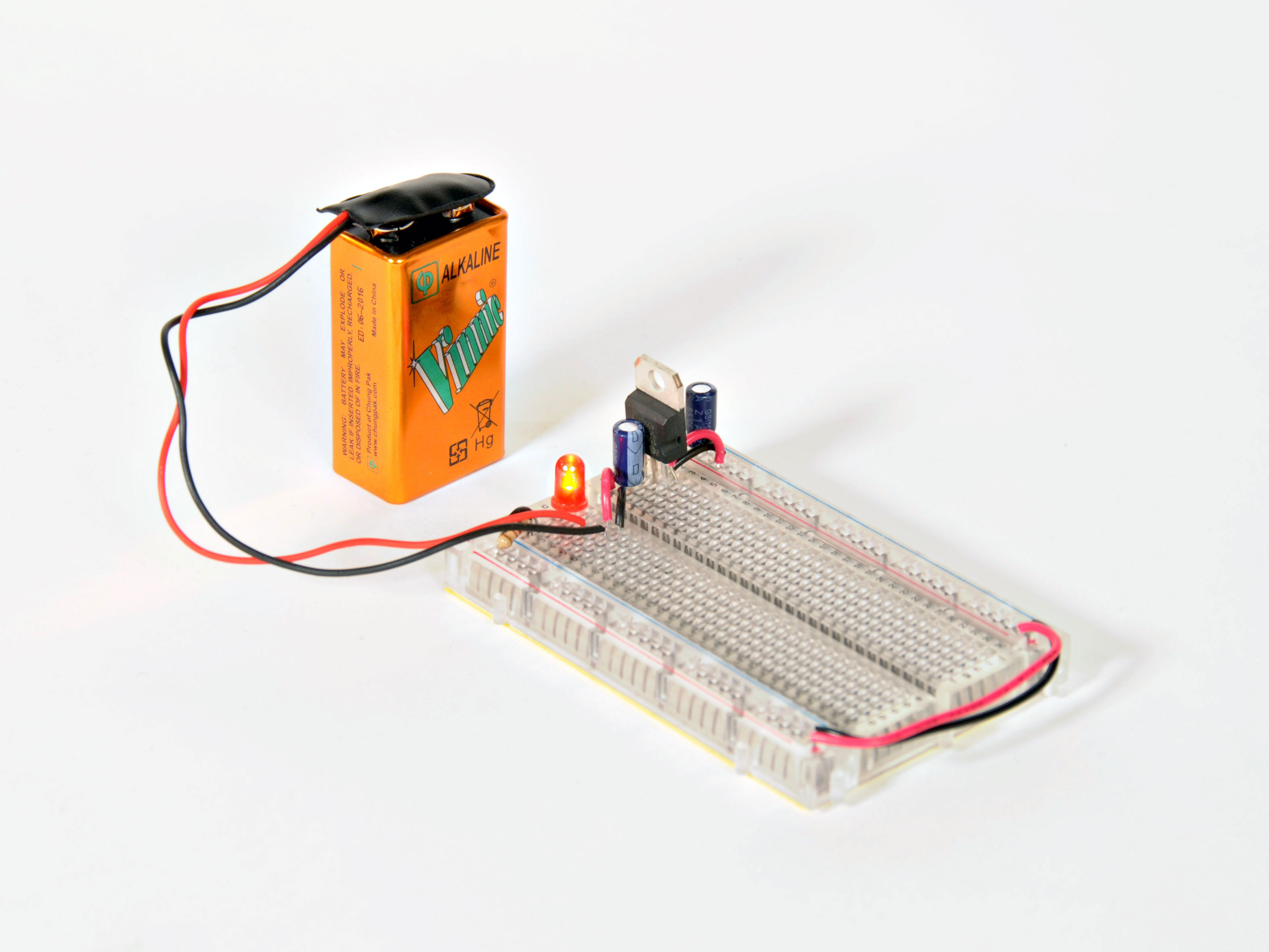
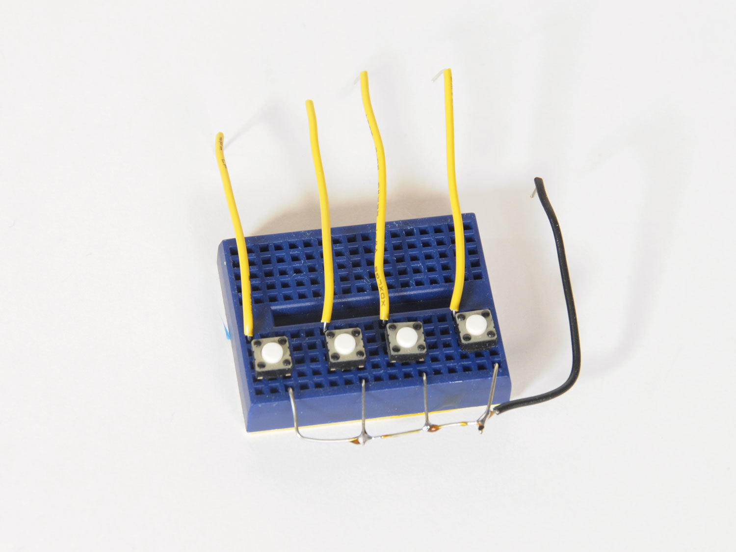
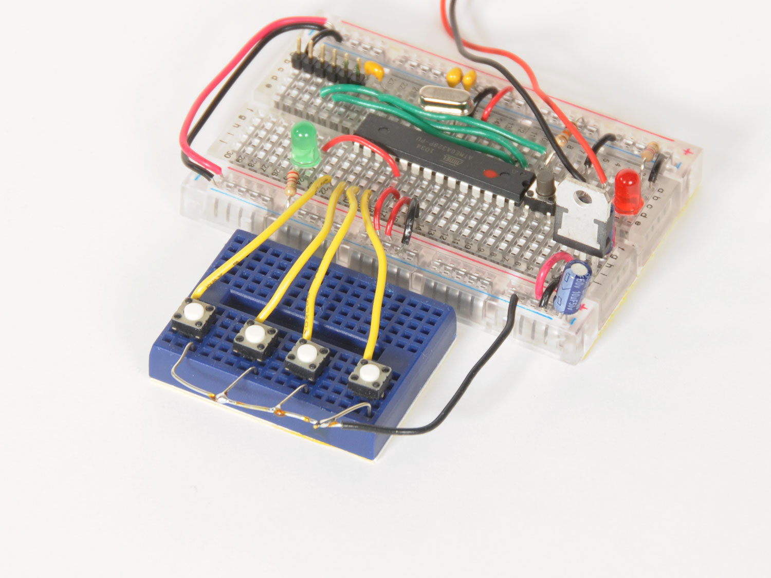
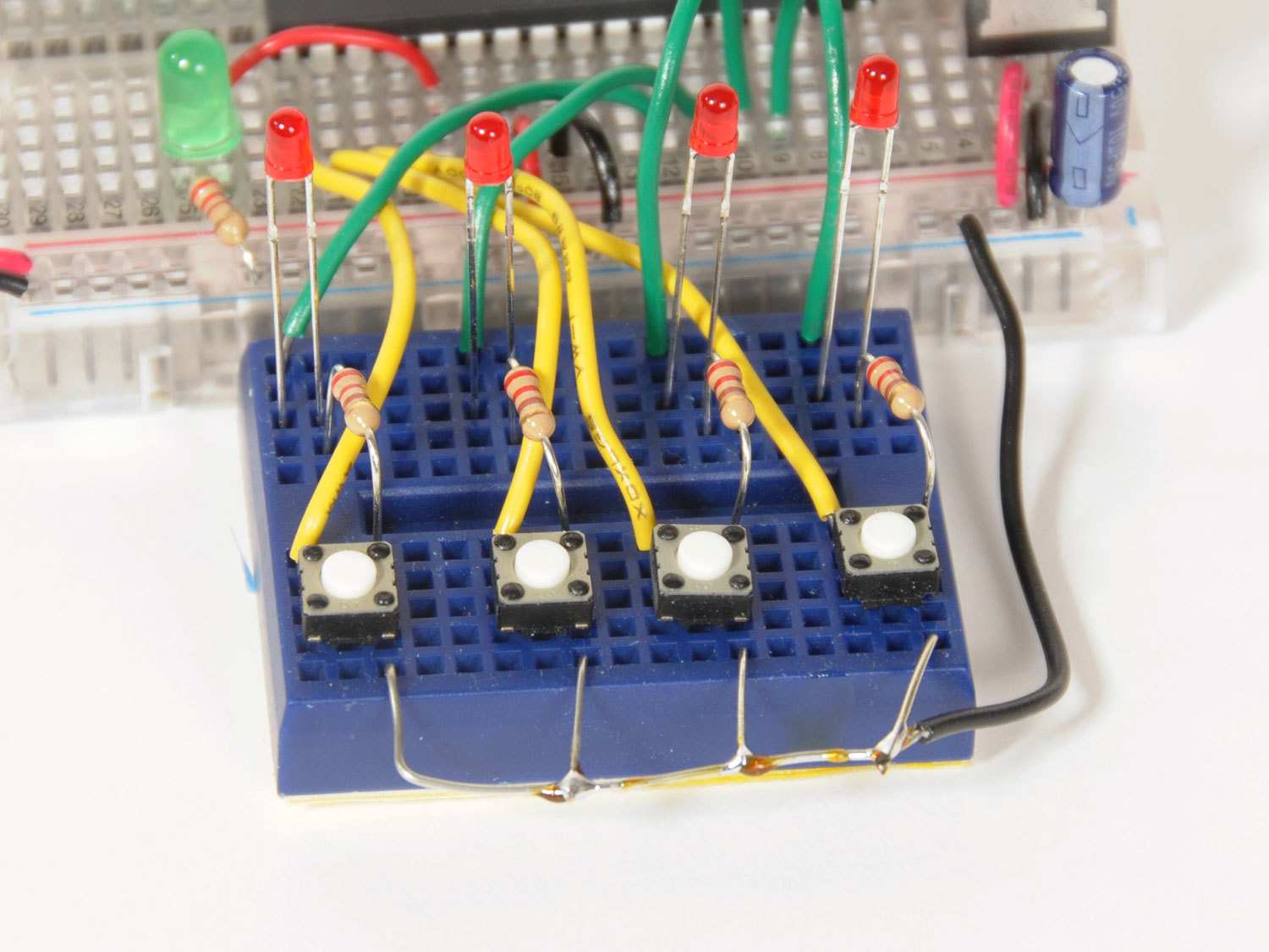
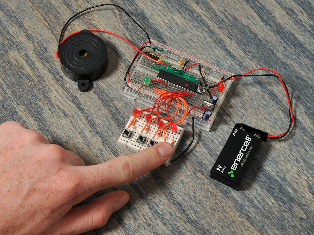
This entire project is built on breadboards, so no soldering is required (though Step 3 is a bit tidier if you solder the wires instead of just twisting them).

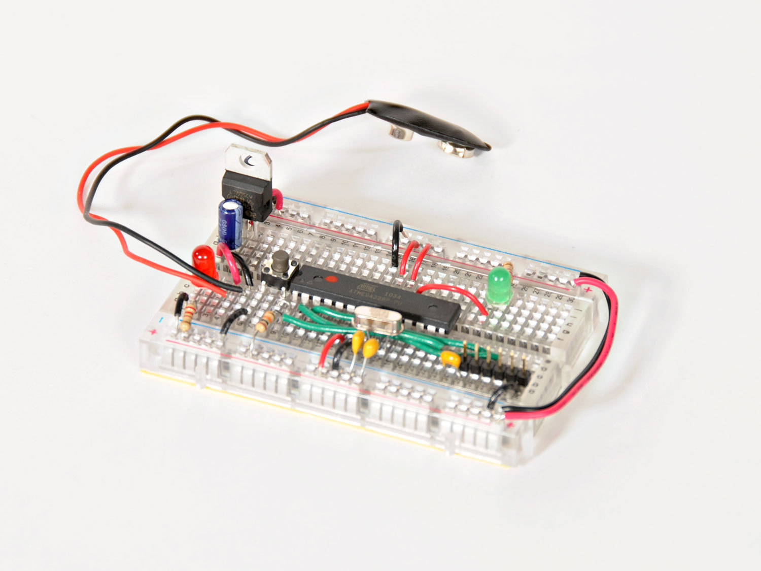
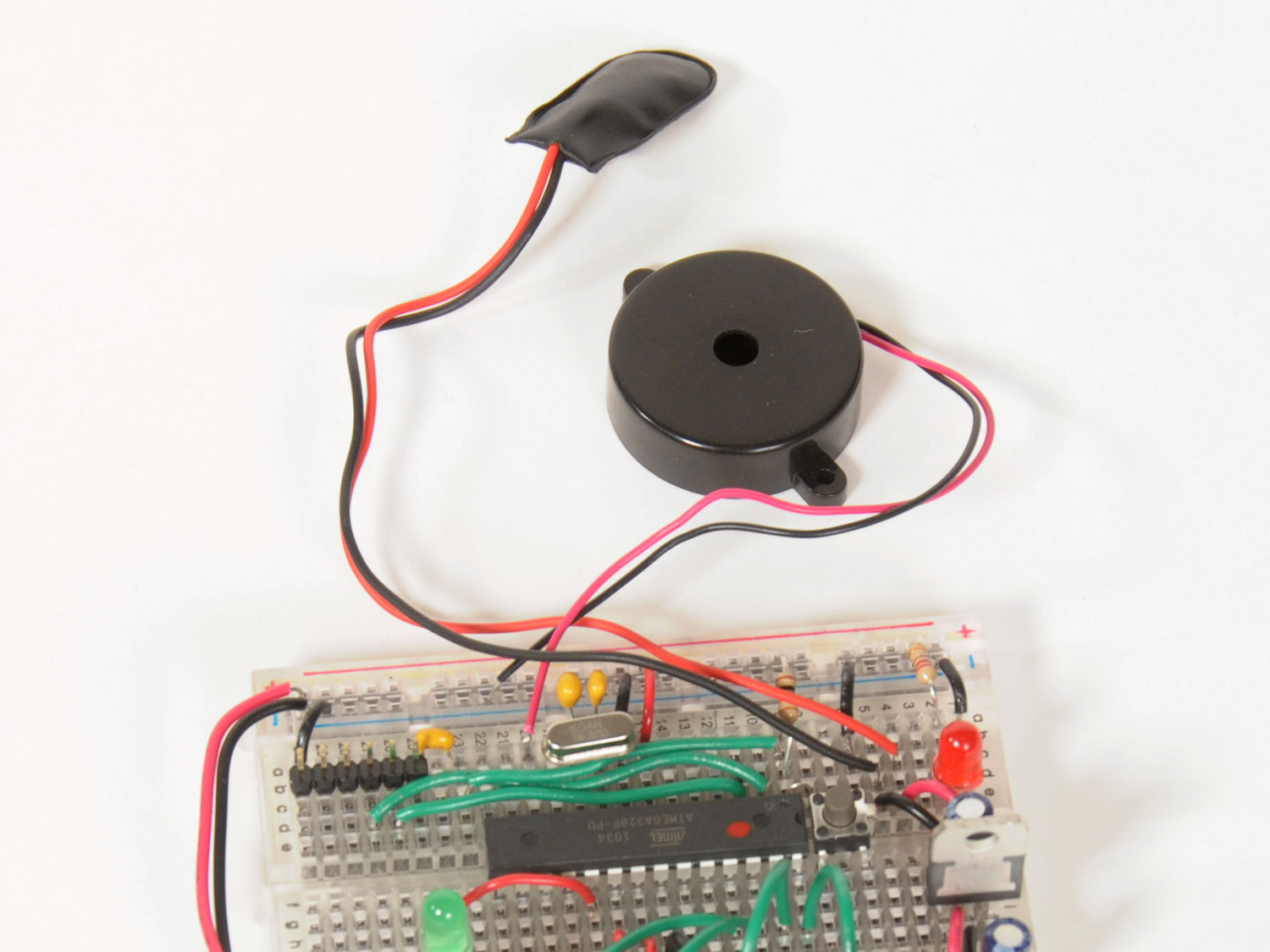
Get ready to build and program your own microcontroller, and relive the dawn of electronic handheld gaming!

Project Steps

Assemble the MintDuino microcontroller.

MintDuino is a breadboard-based Arduino clone. Housed in a mint tin, it includes (nearly) everything you need to create a programmable microcontroller that can control the devices in your world — like a memory game.

I won’t reinvent the wheel on this one, as there is an excellent tutorial right here on Make: Projects at Build a Mintronics: MintDuino. Follow it to assemble your MintDuino.

Just be sure to check your work as you go, keep your chip pins (A5, etc.) straight from your breadboard holes (a5, etc.), and — this is important — make sure the power supply is working before you add the processor chip.

Gather your input/output components.

Tada! Now that your MintDuino is ready to go, it’s time to add the input and output bits to build the game.

We’ll supplement the MintDuino kit with 4 additional LEDs, a piezo buzzer, and 4 tactile switches (not shown here), plus we’ll use the mini breadboard from the Mintronics Survival Pack.

Wire up the game switches.

The Mintronics Survival Pack comes with a mini breadboard. These can be handy, but be warned, they lack power supply strips. And for this project, we need a ground line that extends over the 4 switches.

To accomplish this, strip back a longer piece of the black wire and twist 3 short wires onto one end (I tack-soldered them instead — in which case, OK I lied, there’s a tiny bit of soldering involved).

Then mount the 4 switches on the breadboard as shown, and connect the common ground to one side of each.

NOTE: The switches are not marked and so it can be difficult to work out the orientation. I recommend using a multimeter in conductivity test mode to figure out how to place them on the board.

Also connect short wire leads (I used yellow) to the opposite side of each switch. Now pressing a switch will connect the yellow wire to the common ground.

Connect the switches and buzzer to the MintDuino.

Connect the piezo buzzer to the MintDuino: red wire to pin 6 (b20 on the breadboard), and black wire to ground.

The LED output lines are A2–A5. (Did you know that the analog pins can be used as digital pins, too?) I’ll be using green wires for these.

The switch lines run from D9–D12. I used yellow wires for these. In each case, the lines run 1-4 from bottom to top. So D9 input corresponds to A2 output, and so on. Check with the hookup diagram (third image) for a closer look.

Add the game LEDs.

Place the LEDs on the mini breadboard as shown. In each case, the longer, positive lead is on the left-hand side.

The green wires run to the left-hand lead of each LED.

Finally add four 220Ω resistors (red-red-brown-gold), running from the right-hand lead of each LED to the Ground of its switch.

The switches are wired up to be normally HIGH. When the button is pushed, they are pulled LOW. You’ll notice that no switch pull-up resistors are being used on the breadboard — we’re using the internal 20KΩ pull-ups inside the microcontroller chip for this.

All done! Your game is built.

Program the MintDuino.

Download the “Repeat After Me” Arduino sketch from GitHub. (Arduino programs are called “sketches.”)

IMPORTANT: Download and install the correct FTDI drivers for your computer from ftdichip.com. This tells the Arduino IDE software to add the right “serial ports” for the MintDuino. Otherwise, the Arduino IDE doesn’t provide the right connectivity options and uploading the sketch will return “Error: Programmer not responding.”

Now hook up your FTDI programming cable, open the “Repeat After Me” sketch in the Arduino IDE (free from arduino.cc), and upload the sketch to your MintDuino.

Remember to keep the project plugged into the 9V battery when uploading. Unlike manufactured Arduino boards, your MintDuino cannot pull power from the USB connection off of the computer.

Play

When you connect the battery, the button breadboard will flash one LED and sound a “get ready” tone, then flash all 4 LEDs silently to say “here we go.”

If you’ve ever played Simon or Pocket Repeat, you know how this goes — the game will flash one LED and play a tone, and then you push the button that corresponds to that LED to repeat the flash and tone. Then the game adds a second LED and tone to the sequence, and you press buttons to repeat the sequence. And then a third, a fourth, a fifth, and so on, until your memory fails and you blow it!

The game will then light an LED giving your score: LED 1 for Beginner, 2 for Amateur, 3 for Expert, or 4 for Champ. Good luck remembering 32 in a row if you want to become Champ!

This game is fun and impressively addictive, and it brings back great memories of early electronic games. Of course, being built on a breadboard, it’s not as robust as a store-bought game, so watch where you put your fingers or you might short-circuit a button or knock loose a resistor in your excitement.

Taking your game further.

Just like the 80s games, Repeat After Me will fail you with a rude buzz if you take more than a few seconds to choose a button, and it gradually cranks up the speed as you play. You can change all these values in the Arduino code to customize your game.

The original Tandy Pocket Repeat game (shown here) had 2 game types: the standard game, and a second game that allowed the user to add steps to the sequence, taking turns with the computer. Experiment with the Arduino code and see what you can do!

Other obvious next steps to this project would be to move it off the breadboard and onto a PCB, add a project box, and use more-robust game buttons. Maybe we’ll tackle all of that in a followup project.

Conclusion

Now you know how to build an Arduino-compatible microcontroller on a breadboard from scratch, add some input and output controls, and program a classic game!