
As a student engineer and Maker, I often find myself reverse engineering as part of my design process. Analyzing and researching prior solutions helps me solve problems more efficiently by eliminating guesswork early on, and measuring is often a key part of this process.
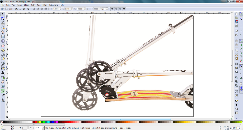
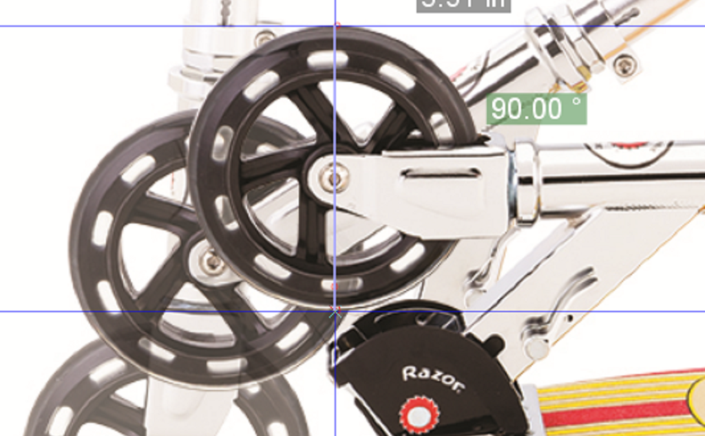
Measuring a physical object usually requires having the object on hand, but with a little creativity it can be done from the comfort of your computer screen. I’m currently working on retrofitting a kick scooter with a brushless motor drive and used this technique to make measurements before committing to a particular model. While the measurements from this technique are far from perfect, they’re great for first-order estimates or projects where accuracy is not critical.

In this tutorial, I will show you how to use a graphics editing program like Inkscape to measure pictures for reverse engineering. While I’m definitely not the first person to use this technique, I independently came up with the process after seeing a Coordinate Measuring Machine (CMM) when I was taking a machine shop class at a local community college a few years ago. Like many 3D printers and CNC machines, the CMM had a 3-axis Cartesian coordinate system for locating a touch probe. By probing various points on an object, the CMM can be used to scan and create 3D models.

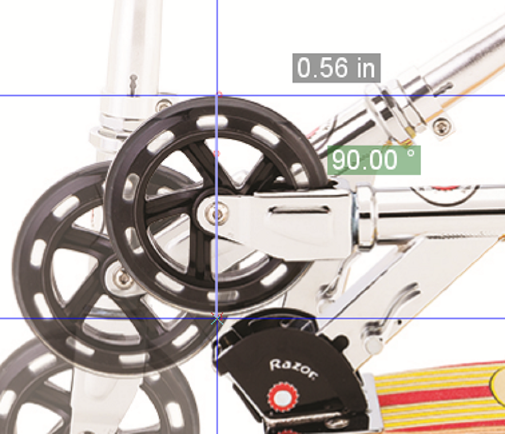
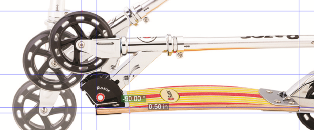
In Inkscape (or your graphics program of choice), you can mimic a CMM using the built-in measuring tools. You will need to measure something with a known size to use as a reference for proper scaling. Then you will use guides to probe and measure points of interest on your picture. This technique can also be done in some Computer Aided Design (CAD) programs, which can be much more efficient for making models.
If you have any questions comment below or feel free to email me at jose [at] makermedia [dot] com.