RoboBrrd’s Characteristics

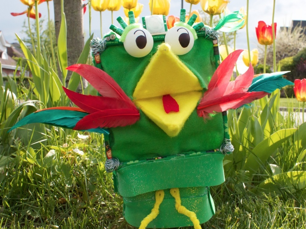
A RoboBrrd is a robot that experiments with human-robot interaction and is created from a limited selection of materials. Inspired by birds, RoboBrrd has a beak and wings that allow it to produce actions based on sensory inputs. The combination of multiple actions create behaviours for RoboBrrd to exhibit. These behaviours provide a way for fun and quirky interactions to occur between the robot and human. It is within the interaction where the robot shows its character.

There are numerous aspects, an example being character, that draw humans toward a robot. In the robotics research world, the study of these aspects in robots is under the umbrella of social robotics. Social robotics explores concepts of how robots and humans can interact and understand each other on a more natural basis.

We attempt to introduce three of these concepts with RoboBrrd:

  • First, the appearance and initial understanding of expectations for the robot. RoboBrrd’s bio-inspired design allows us to anthropomorphize a familiar species. Humans will be able to recognize the key features, and create base expectations of what the robot may do.
  • Second, the robot communicating certain meaningful messages with behaviours to humans through its own movement/output. RoboBrrd allows us to use the degrees of freedom from the beak, wings, and stand to express different behaviours. The LED eyes serve as an indication for the current state of the robot, and can be adapted to illustrate its current mood based on its needs.
  • Third, the robot understanding messages from the human. RoboBrrd will have a motion sensor, some tilt sensors, as well as two light dependent resistors (LDRs). These will allow it to interpret what is happening in its surrounding environment, and do some action based on the interpretations.

Building a robot also uses technical and mechanical aspects. Here are some details that we will learn about:

  • Designing a robot from a limited variety of materials
  • Creating a mechanism to move a beak (converting rotation into somewhat of a linear translation)
  • LM317 voltage regulator circuit
  • TLC5940 PWM shift out circuit
  • Programming servos
  • Programming sensors
  • Programming behaviours

Building a RoboBrrd can be challenging. The first step will help you determine how complex your RoboBrrd will be, and parts you will need.

Here are some video resources that may also help you:

Here are photo resources:

Here are code resources:

Project Steps

Plan what you’re going to build

How complex do you want your RoboBrrd to be? What do you want your RoboBrrd to be able to do? Here are some images of sample configurations.

Be sure to check what parts you already have, and what parts you will need. This will help you in deciding which configuration you want to build.

If this is one of your first robots, going for a smaller configuration may be better, and you can add on more to the RoboBrrd as you go along.

Create the front panel of RoboBrrd

The front panel is the main focal point of this robot. This is where the beak is placed, and the eyes. We will need four pencils and some popsicle and coffee stir sticks for this step.

Cut off the eraser tops from the pencils (1) and create a square (2). We may want to save the eraser tops for later.

Attach popsicle sticks to the pencils (3). Make sure that they are as perpendicular as possible when applicable.

Create and mount the beak on RoboBrrd

The beak of the RoboBrrd is one of the most difficult parts of the robot. We have to take the patience to make this piece as best as we can! We will have to check that the beak fits into the opening that we created in RoboBrrd’s front panel. We will also have to make sure that the two halves of the beak will be slightly touching each other at the back edge of the beak halves.

We will need popsicle and coffee stir sticks for this step, as well as a sharp “poking” tool.

There are two parts to the beak as a whole, the top half and the bottom half. The steps below will be for the top half. To create the bottom half, assemble another top half and turn it upside down.

Start by creating a base triangle (4).

Cut a popsicle stick and poke a hole into it at the end of the straight edge (5). Make sure that the wood doesn’t split. If it does, grab another popsicle stick and try again.

Attach the poked popsicle stick to the middle of one of the sides of the triangle (6). Add coffee stir sticks from the two adjacent edges of the triangle to the poked popsicle stick (7). Add two coffee stir sticks leading to the tip of the beak (8).

Cut a coffee stir stick the length of the space between the two popsicle sticks on the front panel (9). Attach a small coffee stir stick piece (one to each side) connecting the poked popsicle stick and the diagonal beak coffee sticks (10).

Create and mount the beak on RoboBrrd continued

Create the bottom half of the beak by repeating the steps above.

Place the coffee stir stick that was cut in the second-previous step through the hole in the beak (11). Check that the beak (with both halves) measures up to everything in the front panel. Glue the coffee stir stick to the two popsicle sticks on the front panel (12).

Once glued, add two small coffee stir stick pieces to each side of the beak on the coffee stir stick (13). This will help keep the beak in the middle as it is rotating.

Repeat the mounting steps for the bottom half of the beak if not done already.

Grab two popsicle sticks and poke holes at each of the ends in them (14). Attach them to the holes in the “poked hole piece” in the beak halves by using some wire (15).

Take a break, you just completed one of the most challenging parts of the RoboBrrd construction!

Add the other sides

We will need more pencils, many coffee stir sticks, and some wire or string.

Create two squares of pencils (16).

Create a mesh of coffee stir sticks on one of the squares (17). This will be used for the base of the RoboBrrd, where all the servos are mounted and all the electronics sit.

Attach the front panel to the bottom panel (18). Be sure to check that they are attached at 90 degrees as much as possible.

Attach the other square on the back panel on the opposite side of the front panel (19). Try to keep this attached at 90 degrees as much as possible too.

Attach two pencils to the top of the two standing panels (20).

Add some popsicle sticks in for some support (21).

Test the electronics

We are going to take a break from the construction aspect for now, and play with some of our electronics. Testing the electronics that we are going to be using is important, as there is not much room inside of RoboBrrd once all of the electronics are there. We will need all of the electronics that we are planning to use in RoboBrrd.

Test all of the servos and ensure that they are able to be controlled. You can use the “Sweep” example in the Servo library for Arduino. We are going to create a separate power supply to the servos in a later step, we are seeing if they are able to move in this step.

Test all of the LEDs to ensure that they can light up. You can use the “Fade” example in Arduino.

If you are going to have any sensors in RoboBrrd, be sure to check them as well. You can use the “AnalogInOutSerial” example in Arduino.

Create and mount the eyes

The eyes for RoboBrrd will seem magical because they look white, but with some LEDs we can turn them to any colour we want! We will need two ping pong balls.

Poke a hole in the ping pong balls for the LED to fit into (22).

With the LEDs fit into the ping pong balls, mount them on the front panel of RoboBrrd (23). We should be able to take the LEDs out without any problems. Draw eyes on the ping pong balls (24)!

Attach long wires to the LEDs (so they can reach the back of RoboBrrd without being tight), shrink wrap each of the leads, and glue in to the ping pong ball (25).

Create & attach the wing servo mounts

The wing servo mounts are what hold RoboBrrd’s wing servos in place. They are similar to the mouth servo mount, but are a bit shorter. We will be making two of these, for the left and right wings. You’ll want to duplicate each of the steps, or when finished go back and construct the remaining side. We will need some coffee stir sticks and popsicle sticks.

Check the boundaries of each servo, and ensure that the most degrees of movement will be the side that the wing will be on, and attach the servo horn.

Glue two short coffee sticks (that are a little longer than the servo width) onto the servo mounting tags (26).

Attach the two short coffee sticks onto popsicle sticks (27). Place the popsicle sticks inside RoboBrrd and see how short they need to be for the wings. The wings should be situated below the beak. Cut to the necessary length.

Cut an additional two popsicle sticks to the same length as the previous step.

Cut two popsicle sticks that are a little bigger than the width of the servo + coffee sticks + popsicle sticks construction. Attach these to the pairs of popsicle sticks as a base (28).

Determine how far apart you want these two bases to be. They should be a little longer than the depth of the servo. Cut and glue two popsicle sticks attaching the bases together (29).

Create & attach the wing servo mounts continued

Glue two popsicle sticks attaching the tops of the bases together (30).

Test out the stability of the mount by moving the servo and applying pressure to the sides of the mount. Use your intuition if you want to fix it more to make it more stable.

This is a good time to construct the remaining side, if you have not already.

Now that we have the two servo mounts complete, we need to mount them inside of RoboBrrd. They should be relatively close to the front panel, but not too close if they will be moving against something. When you find the appropriate place, glue the base in!

Create & attach the mouth servo mount

The mouth is the most challenging aspect of RoboBrrd, these steps will be testing your patience. Take a break if you have been at RoboBrrd for a while. Now, we will be creating a mount similar to the wing servos, the steps are similar. We will need popsicle and coffee stir sticks.

Check the boundaries of the servo. The most movement should be near the beak.

Follow the same steps as previous to create the same type of servo mount for the mouth servo.

Determine where the servo mount will be placed inside of RoboBrrd. It should not be too far away from the beak. Mark where it will be placed with a pencil on the coffee sticks on the base of RoboBrrd.

Grab a popsicle stick and poke a hole in the rounded end. Compare the length of the servo arm to the popsicle stick. The popsicle stick should be long enough to completely open the beak when the servo is horizontal (32 (accidentally skipped 31, oops!)). We will refer to this as the servo arm popsicle stick.

If the mouth popsicle sticks cannot reach the servo arm popsicle stick, you may have to extend the mouth popsicle sticks. This can be done by gluing another popsicle stick on them. You will have to poke holes in the ends of the sticks.

When the proper length is found for the servo arm popsicle stick, cut the popsicle stick.

Create & attach the mouth servo mount continued

Attach the mouth popsicle arms to the servo arm popsicle stick with a piece of wire.

Glue the servo arm popsicle stick to the actual plastic servo arm.

Test to make sure that the servo can move without any forcing to the necessary points: overbite, mouth open, underbite (33). If you do have to force the servo to move, check to make sure that the popsicle sticks from the mouth are long enough. Also check to make sure the servo arm popsicle stick is long enough.

Keep adjusting and testing the mouth until it works. You will need patience, but the reward of the mouth working smoothly will be worth it.

Using the markings of where the servo mount will be placed, glue it in. It is hard to fix this step, so make sure to triple check that everything is able to work at that spot.

Congrats! You have mounted the mouth servo! :)

Prepare electronics

Preparing the electronics will depend on what electronics you have for RoboBrrd for your specific configuration. These steps are mainly a check list to make sure you have everything that you need for the next steps.

Arduinos and Proto Screw Shields: Make sure your Arduinos work. If you are using a Proto Screw Shield, which is highly recommended for sanity purposes, you can assemble it with a tutorial here: http://ladyada.net/make/protoscrewshield…

Voltage regulator circuit: You will need a LM317, 240 ohm resistor, 5k ohm trimpot, a battery for external power for the servos, a 10uF capacitor, wires, heat-sink and a screw and nut. This will be necessary for the configurations that use more than one servo, as the servos draw more current than the Arduino can provide.

LED PWM Eyes: If you won’t be controlling the LED eyes with an Arduino, you will need to use a PWM shift out chip to help. You will need a TLC5940, a DIP socket for it, a 2k and 10k ohm resistor, and wires. There are some additional resources here: http://www.arduino.cc/playground/Learnin…

Servo plugs: You will need male headers for the servo plugs. The number you will need is the number of servos in your RoboBrrd configuration, multiplied by 3 (for signal, voltage, and ground).

Wires: We will need lots of wires for RoboBrrd, best type will be solid core, 21 gauge, different colours (red, black/brown, orange, purple, etc).

LM317 Voltage Regulator & Servo plugs

We can’t use the Arduino to power all of our servos because the Arduino does not provide us with enough current. The LM317 voltage regulator is used to provide regulated power from an external battery to our servos. As @infurl suggests, there is also a 7805 chip that outputs 5V. If you are handy with circuits, you may want to check out the 7805!

Before proceeding, check what voltage the servos support. In the following steps, we will be using 5V as the operating voltage for our servos.

We may want to use a female header to insert the LM317. Doing so will make the LM317 easier to replace if it breaks.

If you have spare parts, it might be useful to create the circuit on a breadboard first.

The LM317 works by us supplying a voltage in, some adjustment resistor magic, and finally sending the adjusted voltage out (33).

The LM317 datasheet has an example circuit: http://www.national.com/ds/LM/LM117.pdf We will add in a 10uF capacitor after Vout to smooth the servo voltage.

LM317 Voltage Regulator & Servo plugs continued

Here is our circuit diagram: (34)

Some things to look out for when soldering this circuit:

Make sure you keep track of where Adj and Vin are when you are flipping the chip around

The trimpot has three leads from it. Use two of the closest leads to obtain the trimmed resistance.

The capacitor has the voltage out attaching to the positive side, and to get the smoothed voltage, you attach a wire also to the positive side. The negative side goes to ground.

Once the circuit is complete, we need to test it.

Connect the battery to the circuit. If we see smoke, or if the LM317 becomes hot, disconnect the battery. There is something wrong with the circuit. Go through all of the steps and follow the circuit diagram to find the bug.

LM317 Voltage Regulator & Servo plugs continued

Attach a multimeter (on voltage mode) to the smoothed voltage out, and to ground. As we turn the trimpot, we should see the voltage changing.

Turn the voltage to 5V, or as close as you can get it. For the servos, it is best to be under voltage than over voltage.

For the servo plugs, cut three pieces of male headers for the number of servos that you need. It is easier to solder when the headers are longer, because they don’t have a tendency to be on an angle.

Solder the left side of the headers to their respective pin on the Arduino. It is best to not use the interrupt or UART pins in case they are needed.

Solder the middle pins all together, they are used for the voltage. Also solder a connection from the voltage out capacitor to the middle pins.

Solder the right pins all together, they are used for the ground. Also solder a connection from the ground on the proto screw shield to the pins.

Test the voltage from the servo pins to make sure there are no accidental shorts or reversals.

TLC5940 PWM Shift Out

The TLC5940 PWM Shift out is used for RoboBrrd’s eye LEDs if they aren’t being controlled by the Arduino MEGA. This IC gives you a whopping 4096 levels of PWM, per channel. They can also be daisy chained for more channels. Just as a warning, with my RoboBrrd I had troubles with the Servo and TLC5940 library being used at the same time. You may want to take this into account with your LED decision. If you will not be using the TLC5940, you do not have to follow the steps below.

The TLC5940 circuit can be found here: http://www.arduino.cc/playground/Learnin…

It would be best to use a DIP socket in case anything bad happens to the IC, then it can easily be replaced.

One of the “gotcha’s” to be careful about with this IC is that the LEDs are not going to ground, rather they are going to 5V. It is backwards from how LEDs normally work, because these LEDs have to be common anode.

You can solder the LED wires directly to the board, or use female headers. The chances of the LEDs burning out are quite low, provided everything is okay.

To test the TLC5940 we need to attach an Arduino and run some code. You can find the code here: http://www.arduino.cc/playground/Learnin…

The LEDs should be changing colours. If they are not, go back and check your circuit.

Add sensors to RoboBrrd

The sensors that we will be adding to RoboBrrd will depend on your configuration. Ensure that you will have long wires on the sensors to attach into the proto screw shield without and pulling. Keep them away from the servos to avoid tangling.

If we are adding a light dependent resistor (LDR), you may need to attach either a pull-up or pull-down resistor. All LDRs vary, so it is best to test this on a breadboard first.

If we are adding some tilt-ball switches, you will need a pull-up resistor if you are not using Arduino’s internal resistors. We can find more information about tilt sensors here: http://www.ladyada.net/learn/sensors/til…

PIR sensors sometimes need to have their threshold trimpot adjusted. There are also other interesting changes you can make to the PIR sensor to make it behave differently, check out Ladyada’s PIR tutorial: http://www.ladyada.net/learn/sensors/pir…

To test the sensors, run a sketch that prints the sensor’s value to the serial port. There are some sample sketches that do this in Arduino’s examples menu in the IDE.

Iterative plugging and testing!

Just as a friendly cautionary warning, this is near the end, and it is easy to become excited here that the robot will work first try. Although this does happen sometimes, it is more common for there to be glitches and necessary fixes. Remain patient with the robot, it will work once all the bugs are fixed.

The first thing to test will be that the servos ‘jump’ when the external battery is plugged in. Plug in one servo in the direction according to how you soldered in your servo headers. Be careful not to mix up the signal and ground. If the servo does jump, it means that it is receiving the voltage. If the servo does not jump, it is not receiving the voltage, so there it probably something wrong with the LM317 circuit. Unplug everything, go back and retrace your circuit to find the bug.

Choose the ‘Sweep’ example Servo sketch from the Arduino > Examples > Servo menu. We need to change the pin variable to our current servo’s pin. Upload the code to your Arduino. If the servo does not move, check that it is on the right pin and the connection between the servo and the pin. If it still does not work, there is probablt something wrong with the LM317 circuit. Unplug everything, go back and retrace your circuit to find the bug.

Add more servos into the mix until you have all servos working. If for some reason the servos seem to not be as strong as when they were originally were at the beginning, it may be effecting the output voltage of the LM317. Check the voltage with a multimeter. You may have to adjust the trimpot again to bring it close to 5V again.

When you are done testing the servos, unplug the battery. We will need to determine the limits of each servo later on, but for now they are done. Woohoo!

Test the LEDs by using some fading PWM code or TLC5940 code. If they do not work, check that they are connected to the correct pins. If the TLC5940 still does not work, double check the circuit to find the bug.

We already tested the sensors before, but we can check them again. Use some Arduino example code to print their values out to the terminal. If the sensors do not work, check that they are on the proper pin, given voltage and a ground connection.

Iterative plugging and testing! continued

When all is good, begin the boundary tests for the servos. Using the ‘Sweep’ example from the Arduino Servo library is a good place to start. We need to set the upper and lower boundary positions for each servo so that they do not overwork themselves by trying to go someplace where they do not go.

The easiest way to do this is by seeing where the servo is at 0, 90, and 180 degrees. From here, you can gather information about what angle the servo is when it is up, and when it is down.

Take 30 degrees off of each boundary to see if it alleviates some of the stress on the servo at any points. Once the servo is not forcing itself (you can tell if it is by the noises and heat exhibited by the servo), be sure to write down the boundaries. These will be useful for when we will be making behaviours for the RoboBrrd. Continue this process for each servo.

Now that we have the boundaries, the LEDs and sensors are working, we have a functional RoboBrrd! Congrats!

Tidy up & decorate

We will be heading back to the design of RoboBrrd to tidy it up and also decorate it. For decorating my RoboBrrd, I used felt, foam, pipe cleaners, and feathers. Use your imagination! What do you want your RoboBrrd to look like?

The best way to felt the beak is with three pieces. Two of them for the beak triangles, and the third one for attaching the beaks together. Adding a tongue is also nice for effect (35).

If you have a RoboBrrd that has a stand, be careful of the different degrees of freedom when decorating. You don’t want to prohibit any movement with decorations.

The wings are triangles on popsicle sticks (36) with added feathers. You can attach the popsicle stick directly to the wing’s servo arm with glue.

Using velcro on the top and back panels with felt will provide an easy way to access the insides quickly without destroying anything.

On the back panel, you will want to make sure that you have holes for whatever cables you may need to insert. For instance, a hole for the USB cable for the Arduino.

The rest of it is up to you! Go crazy!

Code Basic Movements

Before jumping in to more complex behaviours, we will want to make sure we can make the RoboBrrd perform basic movements at first. You can see example code for my RoboBrrd on Github. Here is a helpful list to get you started:

Open beak: Open the beak from a starting position to go to the fully open position. If you are up for a challenge, instead of a starting position you could try any from any position.

Close beak: Close the beak from the open position to the overbite position.

Left/Right Wing Up/Down: Set the position of the wings to go up and down.

Turn left/right: If you have a base, turn fully to the left/right.

Tilt up/down: If you have a base, have RoboBrrd slowly tilt up and down. Tilting is tricky because we have to remember that there is a lot of mass above that point of rotation, so the speed of the movement can lose control if we go too fast.

Whatever else you think you will need, this will be a good point to add it here!

Code behaviours

We need to create some behaviours in RoboBrrd’s program to showcase the hard work that we have done to bring the robot to life! I encourage you to make your own creative behaviours for RoboBrrd. Here are some ideas to get you started:

Motion detected behaviours: Have RoboBrrd flap its wings and make noise whenever the PIR sensor is triggered.

Light behaviours: Have RoboBrrd move whenever a certain LDR is triggered. Maybe make it play peek-a-boo if both LDRs sense darkness!

Chirping behaviours: Have RoboBrrd make different sounds at different moments in time. Maybe make it chirp some movie theme tunes!

Passive behaviours: Make RoboBrrd do slight movements with its wings and beak. This allows others to realize that RoboBrrd is “alive” and they will be able to interact with it.

Mesh behaviours: Add an Xbee to RoboBrrd and have it interact with your computer and the internet, or other robots! This is a more complex step, but it provides much fun. You can see example code for this in depth at RobotGrrl.com.

Custom behaviours: Think of some new and interesting behaviours and implement them! Have fun!

Share

Share what you made! What behaviours does your robot have? What worked? What didn’t work? What was challenging? What did you learn? We all would love to know :)

Conclusion

Whichever RoboBrrd configuration you built, hopefully you learned more about robotics with it!

Keep up to date with more RoboBrrd videos on RobotGrrl.com!