


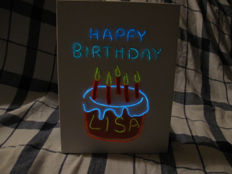
Most EL wire displays are static, because they use an inverter that simply turns the EL wire on (i.e. constant-on). Sound-reactive inverters are available, but most of these are only “single channel”, so the wires are either all on or all off. To really make your display dynamic you need an inverter with multiple output channels, but these are quite expensive. Fortunately, you can make your EL wire decoration more animated inexpensively by reusing the inverter from a “graphic equalizer” T-shirt (a.k.a. T-qualizer) to drive five separate EL wires at five different volume thresholds.
Projects from Make: Magazine
Simple, Cheap, Multi-Channel, Sound-Reactive EL Wire
By reusing the inverter from an EL panel "graphic equalizer" T-shirt, you can turn on five separate EL wires at different volume levels. This is a very easy way to make an EL wire decoration dynamic.

Demo Video and Obtaining the Inverter
Before you get started, follow this link to watch a video of a multilevel, sound-reactive EL wire decoration in action.
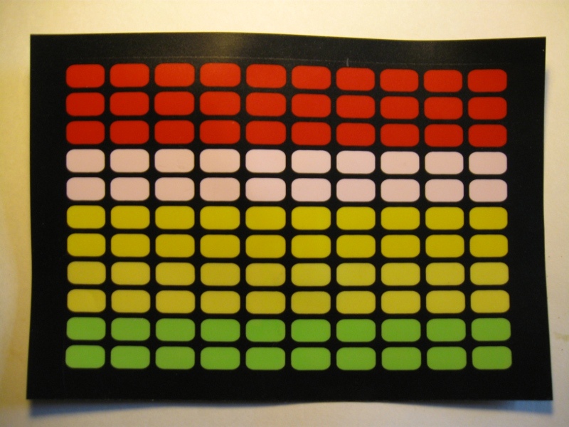
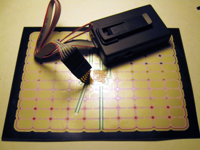
A replacement EL Panel and inverter for a “graphic equalizer” T-shirt can be purchased for only about $7.
All we have to do to use the inverter to drive the EL wire is copy the connector used by the EL Panel. This connector is a 7×1 crimp terminal housing connected to ribbon wire.


Remove the insulation from your EL wire. The corona wires are very easy to accidentally cut so be careful. Here’s a link to a good guide on how to strip EL wire properly.
Use a knife or razor blade to scrape away the phosphor from the core wire.
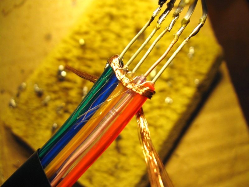
Since the corona wires are further back, cut the ribbon cable so that the five inner wires are shorter than the two outer wires.
Place heat shrink tubing onto each piece of EL wire, but don’t shrink it yet.
Solder the five inner wires of the ribbon cable to the core wires.
Shrink the heat shrink around the core wires’ solder joints. (I used tape to insulate the joints. That’s why you don’t see heat shrink in the picture.)
Use copper tape or copper braid to connect the corona wires with solder. Solder the outer two wires of the ribbon cable to the copper braid.
Insulate everything with hot glue or a large piece of heat shrink tubing.
Making the Connector
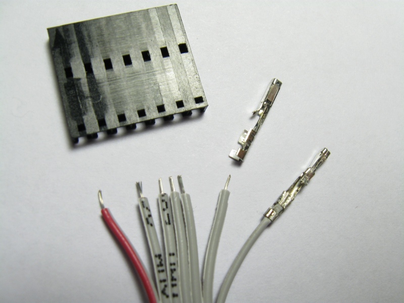
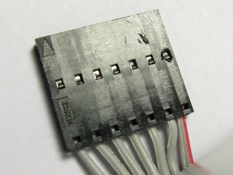
Strip the individual ribbon cable wires and attach the female crimp terminals. There is a special tool called a crimper for attaching these terminals, but a pair of pliers with knurled jaws will also work. Here’s a link to a very detailed article explaining how to attach female crimp terminals.
Insert the terminals into the housing so that the terminals’ metal tabs click into the holes running along the middle.
Test It and Make an Animated Display!

Connect the EL wire to the inverter and test it out. This inverter will not run long lengths of EL wire. It runs five strands each four feet long very well. I’m not sure what the maximum length is.
Make sure never to run the inverter without EL wire connected to each output. The inverter must have a load to prevent it from damaging itself.
Make an animated EL wire display! Have fun!
For instructions on how to make a Musically Animated, EL Wire Decorated Gift Box follow this link. Be sure to watch the videos!


