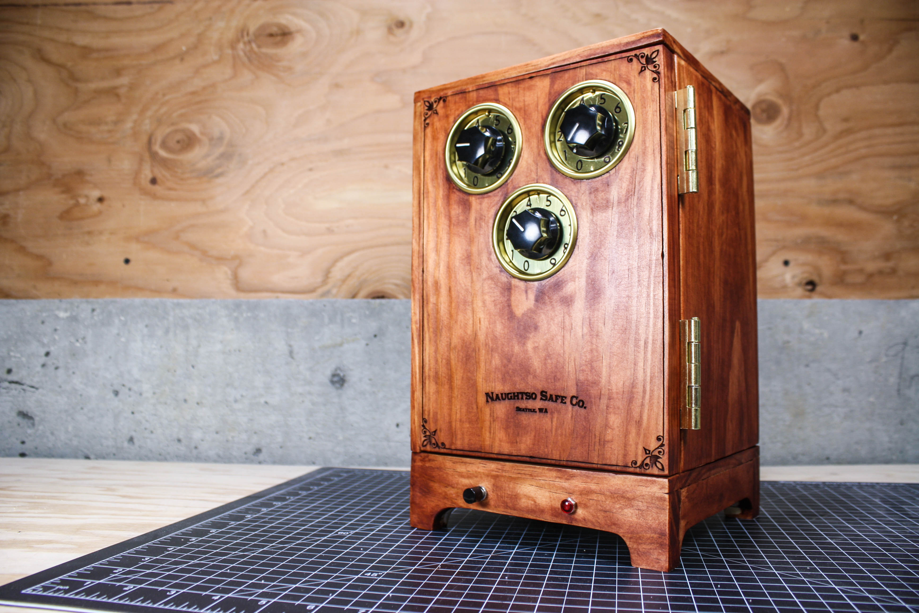
Living in the age of affordable microcontrollers and dirt-cheap single board computers is a wonderful thing, but sometimes writing all of that complex code can be tiresome. Once in a while it’s nice to drop the software side and explore what can be done with simple logic chips, and this custom combination electronic safe project will do just that. In this project we’ll use comparators, AND gates, simple woodworking skills, and hardware-store cleverness to create a three-dial safe that can only be opened with your secret combination.

Before we get into the actual construction of the device, it’s a good idea to walk through the components and basic design of the circuit.

Circuit Diagram

Comparators are devices that compare an input voltage with a reference voltage, and change their output voltage if the input is higher than the reference. In our circuit, we’ll be using multiple comparators in an arrangement that’s called a window comparator.

Window comparators are used to compare an input voltage with two different reference voltages, and change its output if the input is between the reference voltages. In essence, the two reference voltages create a “voltage window,” and the window comparator tells us if the input is within that window.

For this project, the input voltage for the window comparator will come from a variable voltage divider that is controlled by the dial on the front of the safe. Our reference voltages will come from two additional variable voltage dividers that are inside the safe. Since the reference voltages can’t be changed without access to the inside of the safe, they can be set to a “secret” voltage window that is based on a chosen dial position.

Since our safe will have three dials, we’ll need three window comparators, and a way to determine if all three of their outputs are HIGH. This is where our AND gates comes in.

An AND gate will only output a digital HIGH voltage if all of its input voltages are HIGH. Our circuit will feed the outputs of the window comparators into a chain of AND gates that will result in a single HIGH voltage only if all three of the window comparator outputs are HIGH. This resulting HIGH voltage will turn on a power transistor that controls a geared DC motor, which will unlock the door to the safe.

Our safe door lock mechanism starts with a cam on the shaft of a geared DC motor. When this cam rotates, a spring-loaded latch that rests on top of it will angle downward, releasing the latch from a catch hook on the inside of the safe door.

This complex project does require some experience with basic woodworking and simple electronics, but at the end you’ll have a custom-built, electro-mechanical project that you’ll be proud to put on your shelf.

IMG_3851

NOTE: While it may go without saying, this project is not meant to safeguard valuable objects.

Project Steps

Cut the box pieces

Before building the circuit for the safe, you’ll first need a box. While these instructions will guide you through building your own box using basic woodworking skills and tools, you can use a large cigar box or any other box that the circuit board and latch mechanism will fit into.

Our box will be made from a single 6′ long 3/4″ x 7 1/4″ board. You can find these boards at your local lumber yard or big-box store.

Using the saw of your choice, cut all of the pieces in the attached cut list.

In order to make assembly easier, label the pieces as shown in the cut list. Be sure to keep the scraps, as they will be used later.

Download the entire cut list for easy access. It’s a good idea to print out the page for quick reference.

http://cdn.makezine.com/make/WeekendProjects/TheCombinator/CADiagram.pdf

Cut the rabbets

To make putting the box together easier, we’ll cut step-shaped recesses, called rabbets, into some of the pieces. These pieces will become the sides, top, and bottom of the box. Cutting rabbets is usually done with a table saw, though a hand saw can be used as well.

Take pieces A and H, and mark one side of each with lines 3/4″ from all four edges. Cut these lines 3/8″ deep, and then make a 3/4″ perpendicular cut in from the edges to create the rabbets on all four sides.

Now cut a rabbet as described above into each of the two long sides of piece B.

Finally, cut an identical rabbet into one of the long sides of piece C.

Clamp and glue top, sides, and back together

Assemble pieces H, D, B, and C together as shown in diagram 1 on the Cut Sheet, and make sure that they fit together as expected. If necessary, trim or sand the pieces so that the edges fit together flush.

Glue pieces H, D, B, and C where the pieces meet, and clamp them together. Do NOT glue piece A (the bottom) as we will be attaching the circuit board and latch mechanism to it in later steps.

Set the clamped pieces aside to let the glue dry.

Build the motor mount

Print the template, cut out the piece labeled “Motor Mount,” and use a glue stick or spray glue to attach the template to piece I. Drill out the holes indicated, then glue and clamp pieces I and J together as shown in the picture above.

Place the geared motor with the leads facing you and solder a red wire to the top lead and black wire to the bottom lead. The wires should be around 5″ long, and I recommend putting a dab of hot glue on the motor leads, as they can break if moved too much.

Once the glued motor mount has dried, drill two 1/8″ holes in the top of the large half of the motor mount, being sure to avoid all previously drilled holes. Use two small zip ties to secure the motor to the motor mount, with the red wire on the top, as shown in the picture above.

Motor mount template:

http://cdn.makezine.com/make/WeekendProjects/TheCombinator/Templates.pdf

Build the latch spring

In order to keep the door of the safe shut, we’ll build a latch mechanism that is actuated by a DC motor and a cam. To make sure that the latch stays in the “up” position, we’ll build a spring mechanism out of a 3/16″ toggle bolt clamp and a 1″ corner brace.

Place the corner brace on a flat surface, and hold the wider wing of the toggle bolt clamp beside it. Mark the toggle bolt wing through the hole on the corner brace, and drill a 3/16″ hole through the mark.

Drill two 7/64″ holes in the other wing of the toggle bolt, about 1/4″ away from each other lengthwise.

Put a 8-32 1/2″ bolt through the corner brace and the toggle bolt wing holes, and secure it with a lock washer and nut. The 8-32 nut should be just small enough to fit inside the toggle bolt wing.

Cut the latch and cam

Cut out the shapes labeled “Latch” and “Cam” from the template and paste them with a glue stick or spray glue onto a scrap piece of wood.

Drill out the hole in the cam using a 7/32″ drill bit.

Using a bandsaw, jigsaw, or coping saw, cut around the templates to produce the shapes. After cutting out the shapes, use a piece of sandpaper to smooth the outsides of the shapes.

Latch and cam template:

http://cdn.makezine.com/make/WeekendProjects/TheCombinator/Templates.pdf

Drilling holes in the latch

Place the end of the smaller toggle bolt wing on the latch 1 1/4″ away from the angled end of the latch, and flush with the side of the latch as shown in the picture above.

Mark the two holes on the latch, and drill holes at the marks with a 7/64″ drill bit.

Mount the motor, spring mechanism, and cam

On the left half of one of the long sides of piece A (the base), draw lines 2 1/2″ and 2 3/4″ from the front edge. This edge will be the front of the safe. Align the front of the motor mount to the 2 1/2″ line, and as far left as possible without the zip tie hanging over the edge, then secure the motor mount to the base with two 2″ wood screws.

Place the corner brace directly beside the motor at the 2 3/4″ line, and secure it to the base with a 1/2″ wood screw.

Drill a 1/8″ hole through the base approximately 1/2″ from the rear edge of the brace. If the batteries die, or the combination is forgotten, this hole will allow a wire to be pushed through to move the latch and open the door.

Put a little bit of hot glue into the hole of the cam, and slide the cam onto the shaft of the motor. Make sure you leave a small amount of space between the motor casing and the cam so that the cam does not hit the small protruding piece of plastic.

Prepare PC board

Before adding our components to the board, we’ll need to cut it to a size that will fit on the base. I made a cut all the way across the holes of row 24, and removed a corner of the board from row 35 to column K.

Enlarge the mounting holes at the corners of the board to make sure that the 1/2″ wood screws will fit through.

Add resistors and IC sockets

Now we’ll start to add components to the board, starting with the resistors and chip holders.

The resistor leads should be placed through the following holes and bent over to keep them in place:

10k resistors:

  • 34N to 34Q
  • 34R to 34U
  • 34c to 34f
  • 35M to 35P
  • 35S to 35V
  • 35d to 35g


1k resistors (these should be mounted vertically, as shown in the second photo above):

  • 48C to 48E
  • 48G to 48I
  • 48O to 48Q
  • 48S to 48U
  • 48a to 48c
  • 48e to 48g
  • 45F to 47F
  • 45R to 47R
  • 45d to 47d

5.1k resistor:

  • 37i to 40i

The IC sockets should be placed in the following areas:


  • Corners at 27P and 33S
  • Corners at 37P and 43S
  • Corners at 27b and 33e
  • Corners at 37b and 43e

Add potentiometers

Before placing the potentiometers, two of the leads must be slightly bent to fit the holes in the PC board. The remaining leads can be snipped off.

Looking at the side of the potentiometer where the pins are, and with the pins pointed away from you, the second pin from the left and the last pin on the right will be used. Bend these pins toward each other slightly, and snip the other pins off.

Place the potentiometer pins in the following locations:

  • 51B to 51D
  • 51H to 51J
  • 51N to 51P
  • 51T to 51V
  • 51Z to 51b
  • 51f to 51h

Add MOSFET, diode, and capacitor

Now the components that have polarities can be placed.

Place the negative lead of the diode at 31k, and the positive lead at 28k.

Place the negative lead of the capacitor at 38k, and the positive lead at 38m.

With the metal side of the MOSFET facing left, insert the top lead into 27i, the middle lead into 28i, and the bottom lead into 29i.

Add jumper wires

There are three colors of jumper wires: black for ground, red for power, and green for signal. For each of the jumper wires, cut and strip a section of wire of the appropriate length.

Place green jumper wires in the following locations:

  • 26T to 28T
  • 29T to 31h
  • 26e to 29f
  • 45G to 44j
  • 45S to 46j
  • 45e to 48j

Place black jumper wires in the following locations:

  • 49A to 49E
  • 49F to 49Q
  • 49R to 49V
  • 49W to 39W
  • 49X to 49d
  • 49e to 39h
  • 33j to 26j

Additionally, one small section of wire should be stripped bare and inserted at location 44A to 46A. This will be the exposed ground wire used later for measuring the voltage dividers when setting the combination.

Place red jumper wires in the following locations:

  • 50B to 50L
  • 50M to 39M
  • 50N to 50X
  • 50Y to 39Y
  • 50Z to 50i
  • 50j to 50m

Add the off-board wires

Finally, the off-board wires can be added. The 3 pairs of green and red wires to the potentiometers on the door should be cut to approximately 18″, the black and red motor wires to 5″, and the black and red LED and battery wires to 10″.

The off board wires should be placed in the following locations:

Green potentiometer wires at
44k
46k
48k
Red potentiometer wires at
44m
46m
48m
Black LED wire
41k
Red LED wire at
41m
Black battery wire at
34k
Red battery wire at
34m
Black motor wire at
28m
Red motor wire at
31m

After soldering the wires to the board, it’s a good idea to twist the pairs together so that they don’t get tangled or mixed up with one another.

Solder all connections

Now it’s time to solder everything together. All of the connections in blue in the diagram above will need to be made. To make this easier, I recommending bending the component leads in the direction of the components they are connected to, snipping off any excess, and soldering it to the pad.

After soldering all connections, place the 74LS08 chips in the top chip sockets with the U-shaped notch pointed down, and the LM339 chips in the bottom chip sockets with the U-shaped notch pointed up.

TIP: Use a permanent marker to outline a few of the connections. Don’t overwhelm the board with lines. Once a few connections are made, draw a few more lines and complete the wire connections.

TIP: Use a pair of pliers as a heat sink when multiple connection points are necessary with one continuous wire.

Install board on base and attach latch to spring mechanism

Place the circuit board on piece A where it will be mounted, and mark the corner mounting holes that were drilled out earlier. Make sure that the board does not overlap the edges of the base.

Place 1/4″ nylon spacers over the marks on the base, then place the circuit board on top of the nylon spacers, and screw the board down with 3/4″ wood screws.

Now that the board is in place, use a small zip tie to secure the latch to the top of the spring mechanism. Make sure that the zip tie is tight, as we don’t want the latch to move unless the motor spins.

Connect motor wires and run wires through base

Trim and solder the corresponding color motor wires from the PC board to the motor, using heat shrink tubing to insulate the connections. I recommend placing an adhesive wire clip on the base to keep the wires from getting in the way of the latch mechanism.

Drill a 1/4″ hole through base near the rear right corner of the PC board, and run the LED and battery wires through the hole.

Cut box stand

The four pieces labeled G1 and G2 will be glued together to form the stand for the box.

Take one of the pieces labeled G1 and trace out the part to be cut away. The shape that’s cut here is quite simple, but feel free to get as fancy as you want!

Cut the shape away, then use the cut piece to trace the pattern to the three other pieces and cut them.

Mount button and LED, and glue stand to base

Decide where the LED should go on the front stand (part G1), and drill a 5/16″ hole. Insert the LED from the front of the panel. The hole should be tight enough that the LED will stay in place.

Cut, trim, and solder two 5″ black wires to the button. Drill a 1/4″ hole in the panel where you would like the button to go, then use a larger drill bit to widen the hole on the back of the panel until the button can be inserted enough that the threads come through the front of the panel. Secure the button in place with the provided nut.

Glue, assemble, and clamp the stand as shown in the Cut Sheet, then glue and clamp the stand to the bottom of piece A.

Add battery pack, and wire LED and button

Insert four AAs into the battery pack, and attach the battery pack to the bottom of the safe with velcro.

Solder and heat shrink the following connections:

  • One black wire from the button to the black wire from the battery pack
  • One black wire from the button to the black battery wire from the circuit board
  • Red wire from the battery pack to the red battery wire from the circuit board
  • Red wire from LED to red LED wire from the circuit board
  • Black wire from LED to black LED wire from the circuit board

Attach the top to the base

Now that all of the internal work is done, the top of the safe can be joined to the bottom.

Spread wood glue on the bottom edges of the sides and back, and place the top on to the bottom base.

Clamp the top to the bottom, and let the glue dry.

Install the potentiometers on the door

We’ll be using three potentiometers for the dials on the door. Since the door is thicker than the mounting threads on the potentiometers, we’ll be inserting closet door pulls in the face of the door, and mounting the potentiometers in them. If you are using your own box, you may be able to mount the potentiometers directly in the door, depending on how thick the door is.

The dials can be mounted anywhere above 4″ from the bottom of the door. Mark where you want the dials to go, then use a hole saw that matches the diameter for your closet door pulls to drill three holes in the door.

Follow the instructions included with the closet door pulls to mount them in the door, then drill a 5/16″ hole in the center of each one.

Install the potentiometers on the door (continued)

Place the potentiometer shaft through the hole from the rear side, and make a mark where the small mounting pin beside the shaft touches the door pull. Drill out the mark with a 7/64″ bit.

Using a hacksaw, cut the potentiometer shafts down to 1/2″, then mount the potentiometers in the closet door pulls.

Attach hinges and mount door

Follow the instructions that come with your hinges to mount them to piece C, then mount the door to the hinges.

Test the door to make sure it opens and shuts easily. Oil or adjust hinges as needed.

Wire potentiometers

Run the pairs of potentiometer wires from the circuit board up the inside of the safe and across to the potentiometers, and trim them to length.

Strip and solder the wires to the potentiometers. The red wire should attach to the middle lead, and the green wire to the left lead.

If desired, adhesive wire clips can be used to keep the wires under control. The wires may move when the door is shut, but it should not interfere with the movement of the door significantly.

Install door spring

In order to make sure that the door springs open when the latch comes down, we’ll need to install a spring mechanism that pushes the door open. To do this, I used a sliding closet door spring.

Depending on the spring mechanism used, you may need to drill an extra hole to attach it inside the safe.

Secure the spring mechanism with a 1/2″ screw in the upper left corner of the safe so that the door compresses it when it is shut.

Install the catch hook

Cut a scrap piece of wood to approximately 3/4″ by 1 1/2″, and drill two 1/8″ holes through it, one on either end. Drill a 1/6″ pilot hole partially through the center of the piece.

Open the door, and on the bottom right of the inside make a line 1 13/16″ from the bottom, and another 2 3/4″ from the side. Center the pilot hole as close as possible to the intersection of the lines, and secure the piece to the door using two 1 1/4″ wood screws through the 1/8″ holes.

Screw a 5/8″ hook into the pilot hole until it is seated against the wood, with the tip of the hook oriented toward the bottom of the door.

Test the latch mechanism

The potentiometers on the circuit board are used in pairs to set the high and low reference voltages for each window comparator. The first two on the left are for one dial, the next two are for a second dial, and the last two are for a third. I recommend using a marker to label the potentiometer on the left of the pair as the LOW voltage reference, and the right one as the HIGH voltage reference.

Twist all LOW potentiometers to their lowest setting, and all HIGH potentiometers to their highest setting, then twist the potentiometers on the door to any middle setting. Pressing the button on the front should now actuate the motor.

Test the latch mechanism by shutting the door and pressing the button to spin the motor and lower the latch. If the door does not stay shut when it is closed, or if the door does not open when the motor spins, the catch hook may need to be unscrewed one twist. If the door gets stuck closed, push a piece of wire through the hole in the bottom to lower the latch manually.

Attach numbers and dials

Place the numbers, letters, or symbols that you want around the closet door pull. These can be added using adhesive vinyl, stickers, paint, or even plain old permanent marker.

Turn all of the potentiometer shafts counter-clockwise as far they will go, and place the knobs onto the shaft. Align the knob so that the line is pointing to the first number, letter, or symbol, and tighten the screw in the side of the knob.

Glue shelf in place

Now that all of the electronics and mechanisms are in place, the last thing to be added is the interior shelf.

Since the wires for the potentiometers run up the side of the safe, cut, file, or sand away the edge until the shelf fits inside the safe and does not pinch or get caught on the wires.

Once you’re sure that the shelf will fit inside the safe, spread glue around the three edges that contact the walls, place it in position, clamp it, and let the glue dry.

Set the combination

With the door open, set the dials on the door to the desired combination.

Using a multimeter, check the voltage of the first dial by pressing the button on the front of the safe, and touching the negative test lead to the exposed ground wire, and the positive test lead to the exposed middle resistor wire. This will be the “dial voltage.”

With the button still pressed, touch the positive test lead to the exposed resistor wire on the left for the “lower” potentiometer, and adjust the potentiometer so that the voltage reads 0.2 volts below the dial voltage.

Repeat the above step for the “upper” potentiometer, setting the voltage to 0.2 volts above the dial voltage.

Repeat the above steps for the other two dials, and your combination will be set!