There’s never a shortage of applications for a delay timer. Outdoors, you may want to switch on a light for just one minute while you get from your house to your car. In the kitchen, you wait for a beep when the food’s cooked. You might want to run a doorbell for a significant interval so you’ll be sure to hear it — or switch off a heat lamp in the bathroom in case you forget.
The problem I have with delay timers is the hassle of powering them. I don’t necessarily want to place one near a power outlet, but I don’t want to worry about replacing batteries, either. CMOS devices use only a tiny trickle of current while they’re sitting there waiting patiently for you to activate them, but still, it bothers me that they suck electricity while doing nothing.
I decided to design the greenest possible delay timer — one that uses no current at all between one cycle and the next. Zero power! If it was battery-powered, a fresh 9-volt battery could last 4 or 5 years.
Figure A: The greenest delay timer in its simplest configuration, allowing you to attach the device of your choice to the contacts of the relay that close when it is activated.
The circuit I came up with is unusual, but simple. When you press a button, it switches on a 555 timer chip, which activates a relay for a fixed interval. At the end of the interval, the relay switches off the timer, and the timer switches off the relay. Does that sound implausible? Take a look at the schematic in Figure A, which I have laid out so that it will be easily transferable to a breadboard.
When the button is pressed, it supplies power to pin 8 of the timer. Because the button is only switching on the timer, not triggering it, I had to add a 10µF capacitor to pass an initial low state through a 1K resistor to trigger the timer on pin 2, after which a 10K resistor maintains pin 2 at a high state.
The timer is wired in monostable (one-shot) mode, to emit a single delay pulse. The pulse goes out of pin 3 to the relay, which I have drawn to show its internal contacts. When the right-hand contacts close, they feed power back to pin 8 of the timer. So now the relay is powering the timer, and will continue to do so after the button is released, because the output pulse from the timer is still running the relay. The timer and the relay are sustaining each other — until the output pulse from the timer ends. Then the relay contacts open, which switches off the timer. At that point, we have zero power consumption, because the circuit between the positive bus and the negative bus is completely open.
Naturally you will need to adjust the output pulse of the timer to suit your application. For testing purposes, I have chosen component values for a pulse lasting slightly more than two seconds. For a longer pulse, just search online for a term such as “calculate 555 duration”, and you’ll find sites that tell you what component values to choose. I suggest you keep the 1M resistor and increase the value of the 2.2µF capacitor. A 56µF capacitor should create a pulse lasting about 1 minute. A 1,000µF capacitor should provide 18 minutes.
The left-hand contacts in the relay can be used to switch anything you like, within limits set by the manufacturer’s datasheet (typically, a couple of amps). A high-wattage light running on 115VAC would be acceptable.
Figure B. The extended greenest delay timer, including a chime when it reaches the end of its cycle.
But what if you want the timer to run in “kitchen mode,” so that it beeps when the timing interval is complete? Can this be done while still maintaining zero power consumption in the dormant state?
Yes, you just need a second timer powered briefly by a large capacitor. In Figure B, I have extended the previous circuit downward. The upper contact on the left side of the relay now receives power from the upper contact on the right side of the relay, and a 1,000µF capacitor charges from the left-hand contacts. Then when the timer pulse ends, the contacts relax and the 1,000µF capacitor discharges into pin 8 of a second 555 timer, which is wired to create a musical chime. The chime lasts about 1 second, until the capacitor exhausts itself. After that, once again, the circuit draws zero power.
Figure C shows a breadboard layout of the full circuit that’s as compact as possible. If you’re in doubt about any of the component values, refer back to the schematic in Figure B.
You can adjust the duration of the chime by increasing or decreasing the value of the 1,000µF capacitor, and you can change the pitch of the chime by adjusting the resistor and capacitor values associated with the second 555 timer. Once again, you can search online for appropriate values.
Figure C. Breadboard layout for the extended greenest delay timer. If you’re in doubt about any of the component values, refer back to the schematic in Figure B.
Of course, in a kitchen timer you’ll want to be able to choose a variety of possible delay values, from maybe one minute to half an hour. Can we do that and still retain our zero-power status? Don’t we need to add a counter and a numeric display?
No, certainly not, so long as you’re willing to be retro and think analog. Simply remove the 1M resistor attached to the first timer and replace it with a 1M potentiometer and a 10K resistor in series. (You need the 10K resistor to avoid the risk of the potentiometer reducing the resistance all the way down to zero.) Now you can adjust the delay simply by turning the potentiometer.
You’ll have to calibrate it by trial and error, but that shouldn’t take long. And think of the payoff you gain, when a guest claims to have a green lifestyle. You point smugly to your timing device and say, “That gadget is using absolutely no power whatsoever.” How could anything be greener than that?
Well, maybe if your timing device used negative power. That is, it would generate surplus power and feed it into the grid. Perhaps you could have a hamster running in a little wheel attached to a miniature generator? But no, you’d have to feed the hamster, and growing the food would consume resources. I think zero power consumption is as good as it gets.
How best to fabricate an enclosure for the greenest timer? Normally I use ABS plastic for project boxes — but for this project, that would be heretical. Out in the yard I found the answer: an old length of 2×4 pine, seasoned by years of harsh Arizona weather (Figures D and E). I ran it through a table saw to reduce its width and thickness (Figure F).
Figure D. A weathered chunk of 2×4 is the starting point for a green enclosure.Figure E. The environmentally challenged exterior of this humble piece of pine needs no sprucing up.Figure F. The underside, sliced and beveled with my table saw.
What about a pushbutton? I wanted something impressive. At my local Family Dollar I found a soft rubber bulb syringe, intended for aspirating mucus from a baby’s nose (Figure G). It was white, but I could make it green. I hoped that latex paint would be flexible enough (Figure H).
Figure G. A soft rubber bulb syringe, intended for the nostrils of infants.Figure H. The syringe made green. The remaining white part will be cut away and discarded (I regret that it was not recyclable).
The actual switch would be mounted under the rubber bulb. I dug out a snap-action switch that I rescued long ago from some ancient piece of hardware. Also, I found a vintage potentiometer. No carbon offsets would be necessary for these reused items (Figures I, J, and K).
Figure I. A snap-action switch is mounted on a piece of ½” square poplar with #2 screws.Figure J. The switch pokes through a hole cut with a Forstner bit to fit the rubber bulb.Figure K. This tiny speaker will be adequate for beeping when the time is up.
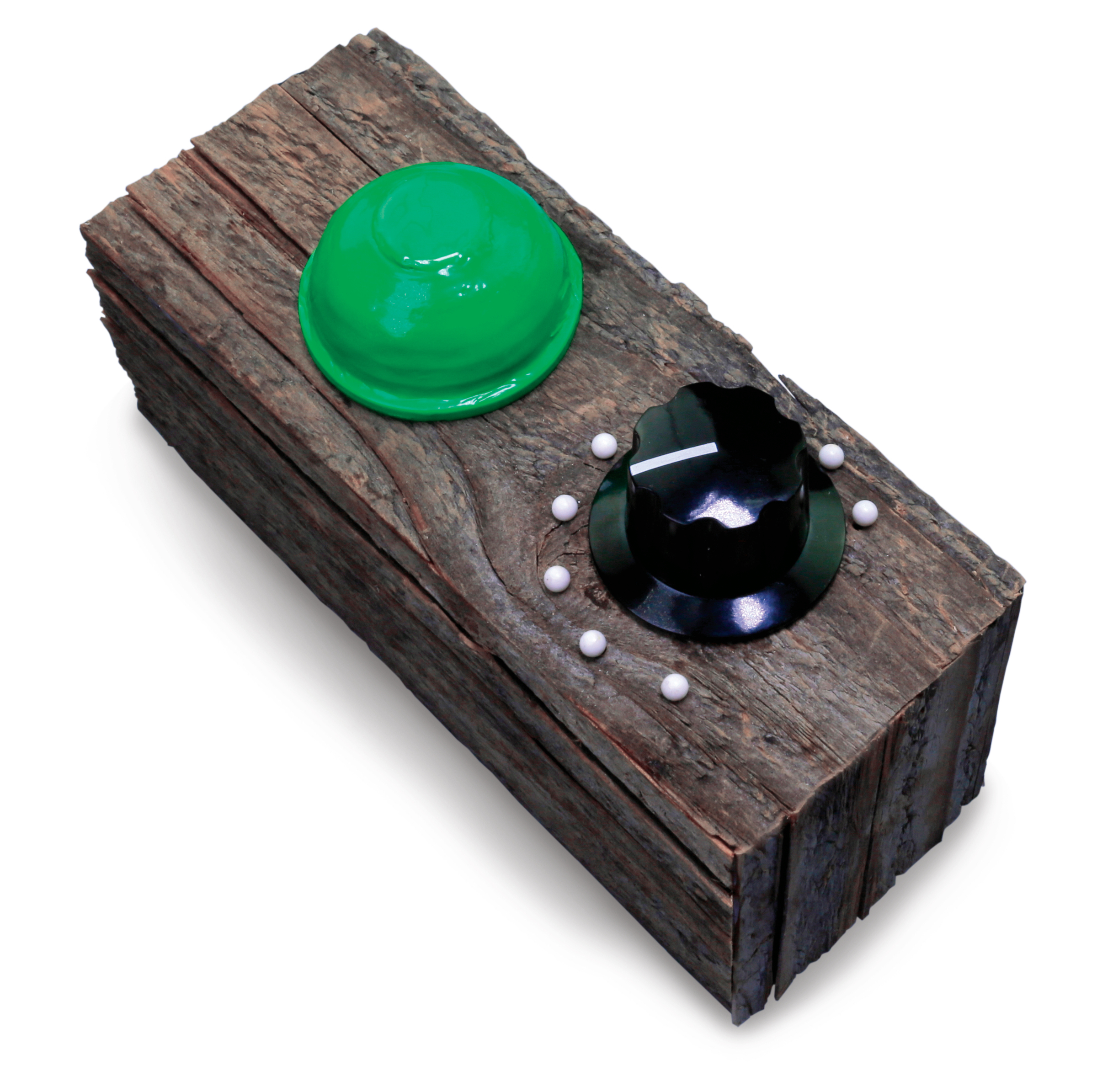
The final enclosure (Figure L) looks as if it might satisfy the most sustainable community.
Figure L. The finished enclosure, glued together with epoxy. Push-pins mark intervals of approximately 1 minute around the retro-style knob. So far, the green paint hasn’t flaked or peeled, but when it does, that could just add to the reused and recycled appeal.
Our websites use cookies to improve your browsing experience. Some of these are essential for the basic functionalities of our websites. In addition, we use third-party cookies to help us analyze and understand usage. These will be stored in your browser only with your consent and you have the option to opt-out. Your choice here will be recorded for all Make.co Websites.
Allow Non-Necessary Cookies
Escape to an island of imagination + innovation as Maker Faire Bay Area returns for its 15th iteration!
Buy Tickets today! SAVE 15% and lock-in your preferred date(s).


![Figure-A-[Converted]-Newest](https://i0.wp.com/makezine.com/wp-content/uploads/2015/06/Figure-A-Converted-Newest-620x726.png?resize=620%2C726&ssl=1)
![Figure-B-[Converted]-New](https://i0.wp.com/makezine.com/wp-content/uploads/2015/06/Figure-B-Converted-New-565x1200.png?resize=565%2C1200&ssl=1)


