This is the first of an eight-part series documenting my build of MakerGear’s Mosaic desktop FDM/FFF 3D printer kit.

  1. the frame
  2. the Y-axis
  3. the X-axis
  4. the Z-axis
  5. the extruder
  6. the build platform
  7. the electronics
  8. the first print

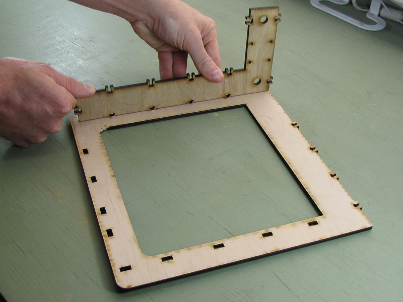
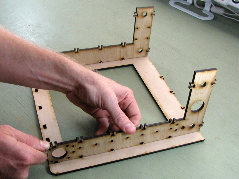
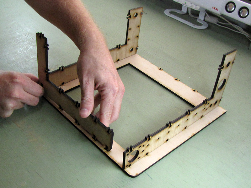
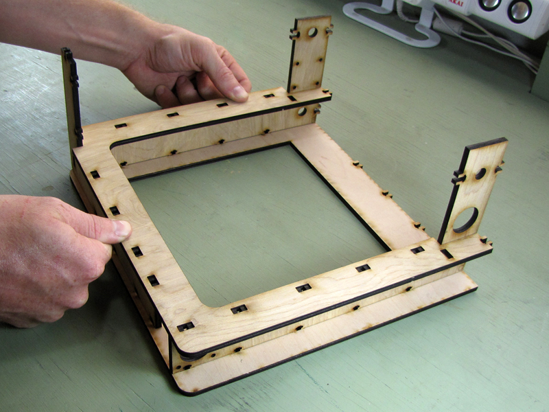
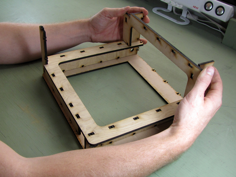
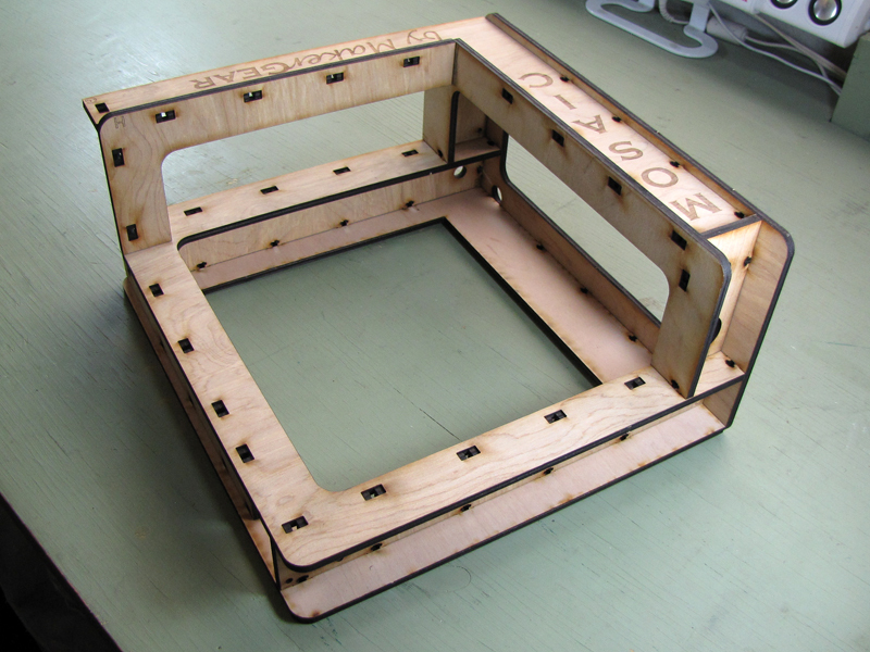
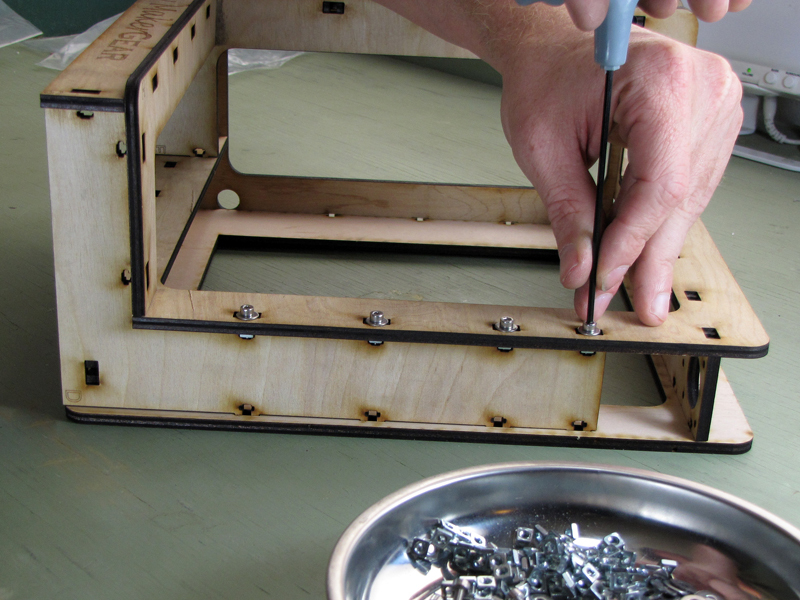
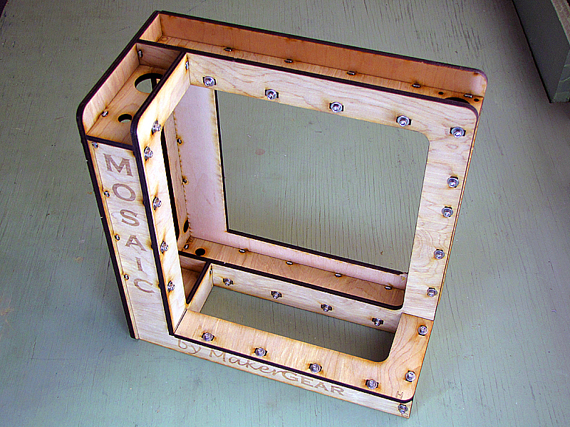
This part covers the assembly of the nine sections of the frame, which are laser-cut from 0.200″ plywood, and the method for securing them using the built-in captive-nut mortise-and-tenon joints.

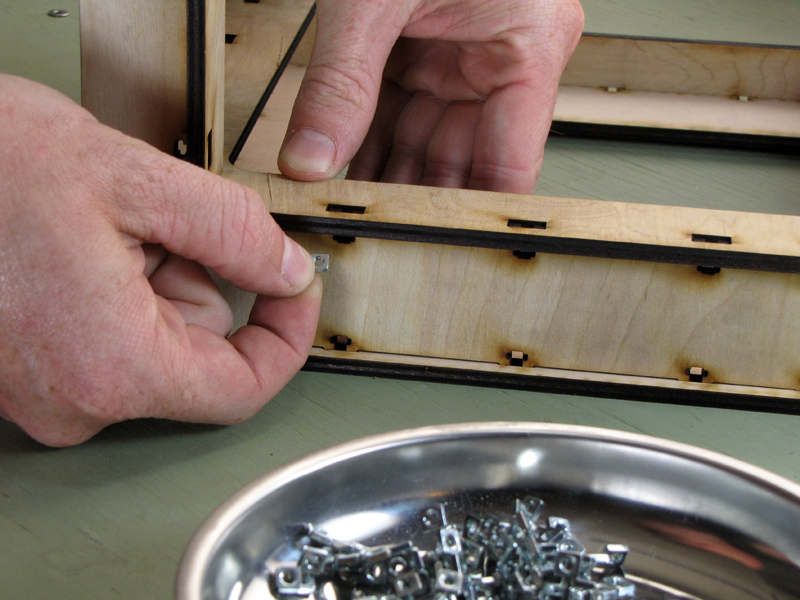
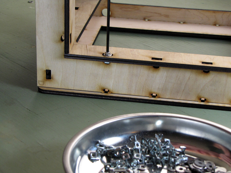
Note: Many builders prefer to insert captive nuts in the frame sections before slotting them together, and, if necessary, to secure them temporarily with tape. In my build, neither measure proved strictly necessary. Using small flat-nose pliers, I didn’t have any problem putting the nuts in place after everything was slotted together. I also found that the nuts fit snugly enough that no tape would’ve been necessary to hold them if I’d decided to insert them before assembly. But your own experience and preferences may of course differ, and it’s worth thinking about before you get started.

Project Steps

Frame sections A-D

Be gentle and patient when interlocking plywood parts. Start at one end of a row of joints, and work toward the other, gently pushing on either side of each tab, as necessary, to align it with the corresponding slot.

Orient “L”-shaped part B with respect to “O”-shaped part A, as shown, and interlock the four split tabs on part B with the corresponding slots on part A.

Part C is similar to part B, but it has five tabs along the mating edge with part A, instead of four, and a large hole in each leg of the “L.” Align the tabs in part C with the slots in part A, as before, and interlock.

Part D is similar to parts B and C, but slightly shorter, and with no round holes. Align it, as shown, and interlock with part A, as before, via four tabs and slots.

Frame sections E-G

Part E is of the same size as part A, but “U”-shaped, with one open edge. Note the orientation of the “notched” corner and the rounded corner, and align thirteen slots in part E with corresponding tabs in parts B, C, and D. Interlock tabs and slots.

Part F is has the shape of a shallow “U,” and interlocks with part E via two tabs, one at the end of each leg of the “U.” A single slot on each leg receives a tab from upright parts B and C. Align and interlock, as before.

Part G is “L”-shaped and bears laser-etched manufacturer’s marks on its outer surface. It has a single slot that receives a tab from part D, and four tabs that mate with corresponding slots in part F. Align all these, and gently interlock.

Frame sections H, I

Part H is “L” shaped, with six slots and rounded corners. It mates with part G by receiving four tabs, and with part D by receiving two tabs. Align these six pairs of tabs and slots, and gently interlock.

Part I is shaped like a tall, narrow letter “O”. It has fourteen slots that receive tabs from parts A, B, C, E, and G, and should be self-indexing to these tabs. Align and interlock, as before.

Secure with nuts, washers, and screws

Each tab-slot pair in the assembled frame is secured with a captive square nut, a washer, and a socket-cap machine screw. There are 57 such joints, total.

To secure a single joint, first insert a square nut into the “arms” of the small cross-shaped slot on the tabbed part. Push the nut into the slot until it is centered across the thickness of the plywood.

The nuts fit closely, and will jam if inserted at an angle. A small pair of flat-nose pliers, though not required, can be extremely useful for gripping and inserting the square nuts.

Pass a socket-head cap screw through a flat washer, and then through the slots in both parts to mate with the captive nut. Tighten the screw securely with a hex wrench, but don’t overdo it.

Repeat this process for each of the remaining tab-slot joints.

Conclusion

Next week: Building the Y-axis!