This is the second of eight guides in a series documenting my build of MakerGear’s Mosaic desktop FDM/FFF 3D printer kit.


This part covers assembly of the Y-axis systems. The largest subassembly in this system, the Y-axis motor mount, comes pre-assembled, and this step consists mostly of decorating it with various components like the linear rail, the stepper motor, and the timing belt.

Project Steps

Prepare linear rail assembly

Your Mosaic kit should arrive with the Y-axis linear bearing pre-installed on the Y-axis linear rail. Be very careful not to let the linear bearing slide off the end of the rail, or the ball bearings it contains will scatter everywhere, and it will be very difficult to reassemble.

Check to make sure the temporary green plastic rail stops are secure at the ends of the linear rail assembly.

Position the linear rail assembly on the pre-assembled Y-axis motor mount, as shown, aligning the five exposed mounting holes in the rail with the corresponding holes in the Y-axis motor mount.

Install long rail mounting screws

Run an M3 x 30mm socket-cap screw through the second and sixth holes in the linear rail, down through the mounting holes in the top and bottom of the Y-axis motor mount.

Being careful not to let the screws fall out, turn the motor mount up on its long edge, as shown, and slip M3 fender washers over the exposed threads of the two socket cap screws you just inserted.

Using a 2.5mm hex wrench on the socket-cap side, and a 5.5mm socket wrench on the nut side, secure each of the two socket cap screws with an M3 nylon-insert locking nut, or “nylock.”

Install short rail mounting screws

Run M3 x 12mm socket-cap screws through the third, fourth, and fifth mounting holes in the linear rail and through the corresponding holes in the Y-axis motor mount.

As before, turn the Y-axis motor mount up on its long edge, being careful not to let the screws you just inserted fall out.

The center bolt takes an M3 fender washer just like those you’ve already installed. Go ahead and put it in place.

Secure short rail mounting screws

The third and fifth bolts emerge very close to the motor mount bulkheads, and require narrow-diameter M3 flat washers. It can be a bit tricky to get these over the bolt shanks, but it’s not difficult if you use a pair of tweezers.

I didn’t have a proper wrench that would both fit the nylocks and fit into the close space behind the third, fourth, and fifth bolts, so I used a small pair of pliers, as shown, to hold the nylocks still while tightening from the other side with a hex wrench.

Install rail end stops

Run an M3 x 30mm socket cap screw through each of two 1/4″ nylon spacers, then through the rail-end-stop mounting holes in the motor mount, as shown.

Flip the motor mount up on its long edge, as before, and secure the two rail-end-stop bolts with nylocks. Note that these bolts do not take washers.

Remove temporary rail end stops

With the permanent rail end stops in place, the temporary green stops are no longer necessary. Remove them with a small pair of pliers, as shown.

Do not discard the temporary green rail stops. If, for whatever reason, you want to demount the linear rail at a later time, they will be useful again, to prevent the bearing from sliding off the end of the loose rail.

Finish mouting the rail with M3 x 30mm socket-cap screws, M3 fender washers, and nylocks.

Install nylon Z-stop bolt

Thread the M4 nylon hex nut about halfway up the shaft of the M4 nylon hex bolt.

Turn the nylon bolt into the threaded brass insert in the motor mount, as shown, until it’s finger-tight against the hex nut you just put on.

Install Y-axis motor

Position the red rubber gasket over the motor mounting holes, as shown. The gasket goes between the Y-axis motor and the mount, for vibration isolation.

Run each of four M3 x 10mm socket-cap bolts through an M3 fender washer, through one of the four motor mounting holes in the plywood motor-mount assembly, through the corresponding hole in the gasket, and into the corresponding threaded hole in the face of the motor.

Tighten the bolts into the threads in the motor face slowly, gently, and carefully to prevent damaging the threads. As the bolts begin to draw up tight, proceed in a criss-cross pattern around the motor shaft to tighten then down the last few turns. Do not overtighten.

Adjusting the timing belt

Unless you are pretty lucky, finding the right tension for the timing belt will require some trial and error. This step illustrates the general procedure for adjusting the belt’s length.

Slip the belt into the jaws of the free belt clamp, adjusting its length as needed. Work patiently and carefully here, and do not pry on or otherwise overstress the plastic jaw. Make sure the belt is seated evenly, at the very bottom of the slot, before proceeding.

Turn an M3 x 16mm socket cap bolt into the holes in the belt clamp. The bolt is a tight fit, and the threads will cut into the plastic a bit.

Start an M3 nylock over the exposed bolt threads, and tighten it down with a loose 5.5mm socket. Be very gentle. The nut is almost unnecessary.

Install the timing belt

This is the step in which the timing belt is actually put under tension. If it is too tight, or too loose, its length will have to be adjusted following the general procedure in the previous step.

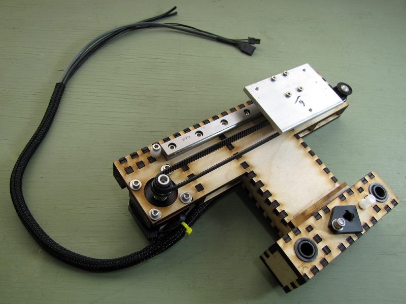
Noting the correct orientation of the white plastic belt tensioner, slip the belt over the fixed drive pulley on the motor shaft.

Slip the belt into the groove of the loose idler pulley, then stretch the belt to slip the idler pulley over the idler shaft. If the belt tension is correct, it will take a bit of force to do this.

The idler pulley gear and the drive pulley gear should be at the same height. If they are not, the belt will tend to ride up and slip off as it is moved. To re-align, simply loosen the drive gear set screw on the motor pulley and move it up to match the height of the idle gear, and then carefully re-tighten the set screw.

With the belt in place, adjust the position of the belt tensioner until it is centered over the linear bearing. Observe the belt as you do so. The rule of thumb for belt tension is: “when you slide the pulley back and forth, the belt should not bulge as it moves around the pulleys.”

If the belt is too tight or too loose, remove and shorten or lengthen it, as necessary, following the procedure in the preceding step.

Install build platform mounting plate

The aluminum build platform plate is symmetrical, so it doesn’t matter which side is up. Note, however, the correct orientation of the long edges. The edge opposite the four bearing mounting holes should hang over the timing belt.

Align the four mounting holes in the plate, the belt tensioner, and the linear bearing.

Run each of four the M3 x 16mm socket-cap bolts through a lock washer, then through one of the holes in the mounting plate (loose fit), one of the holes in the belt tensioner (tight fit, threads will “bite”), and into one of the threaded holes in the linear bearing. Be very careful not to damage the threads in the bearing. Stop short of final tightening until all four bolts are installed.

Once all four bolts are correctly installed, apply final tension in a criss-cross pattern. Do not overtighten.

Conclusion

This completes assembly of the Y-axis system. Next: Building the X-axis!