This is the third of eight guides in a series documenting my build of MakerGear’s Mosaic desktop FDM/FFF 3D printer kit.


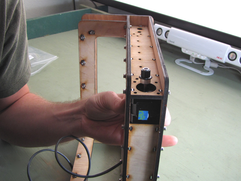
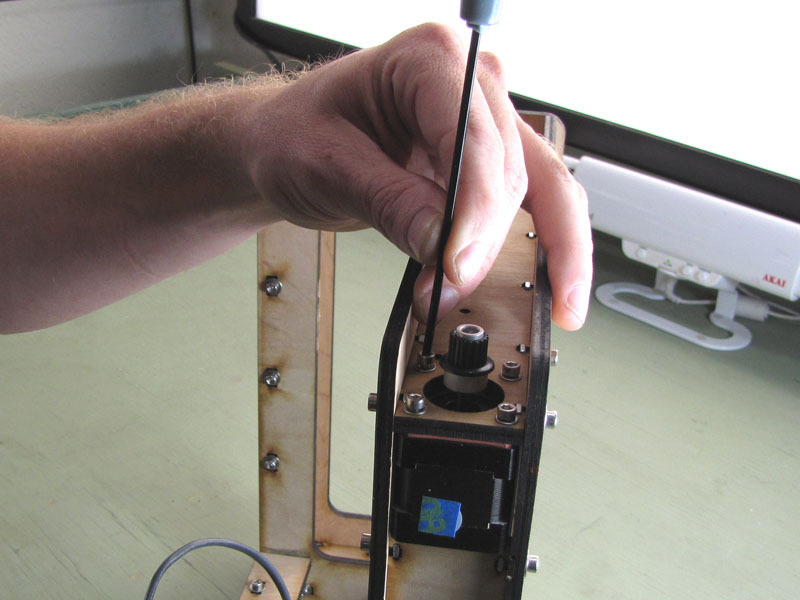
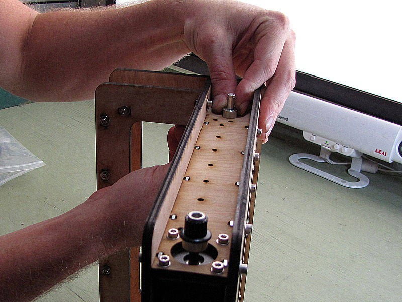
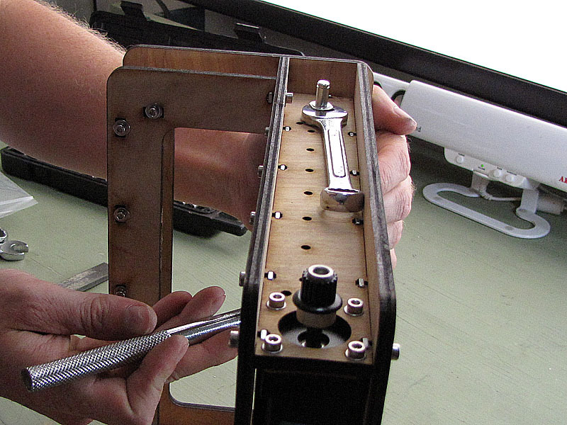
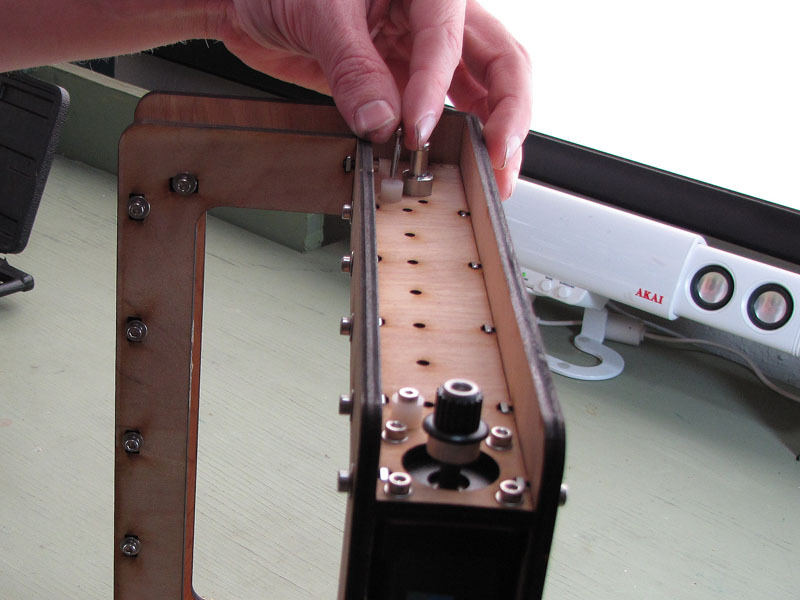
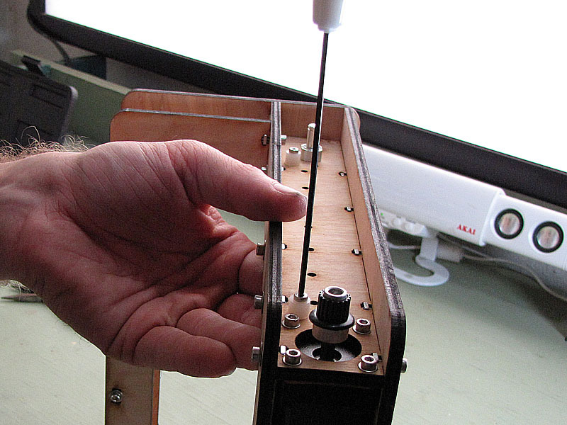
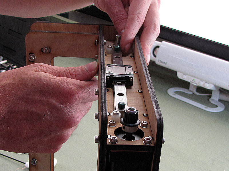
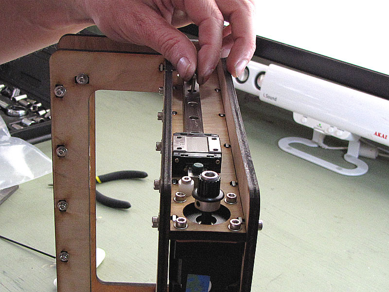
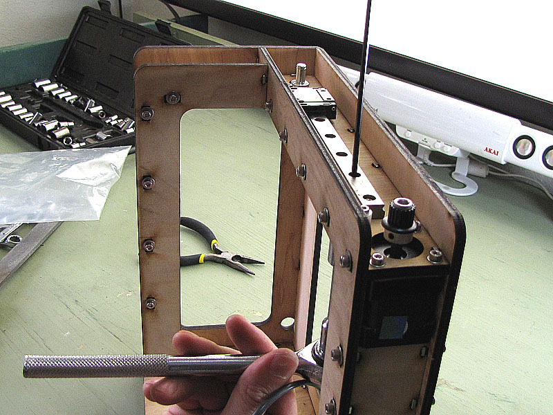
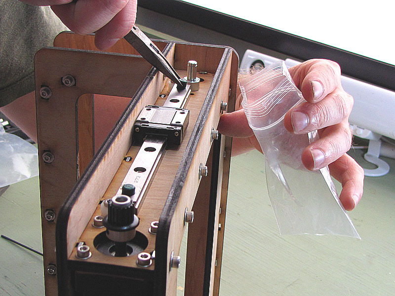
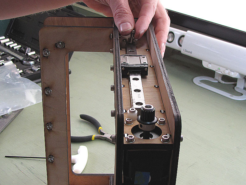
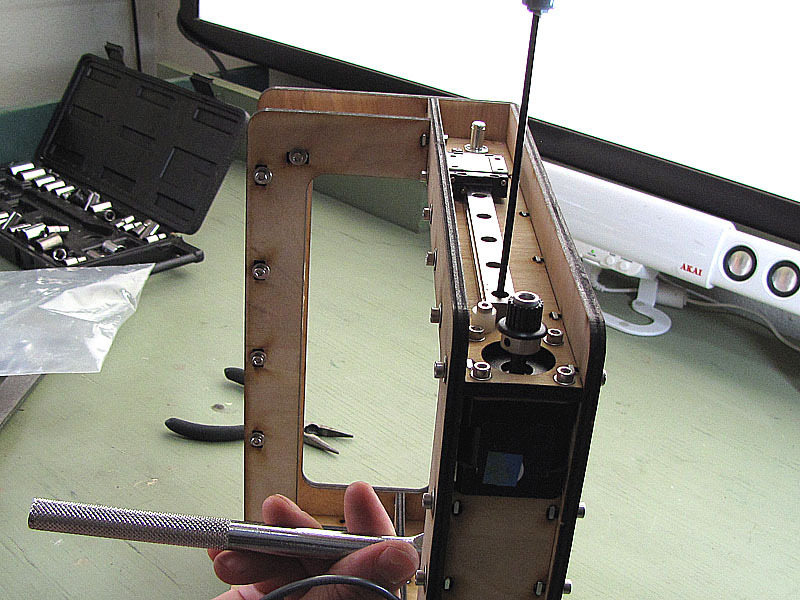
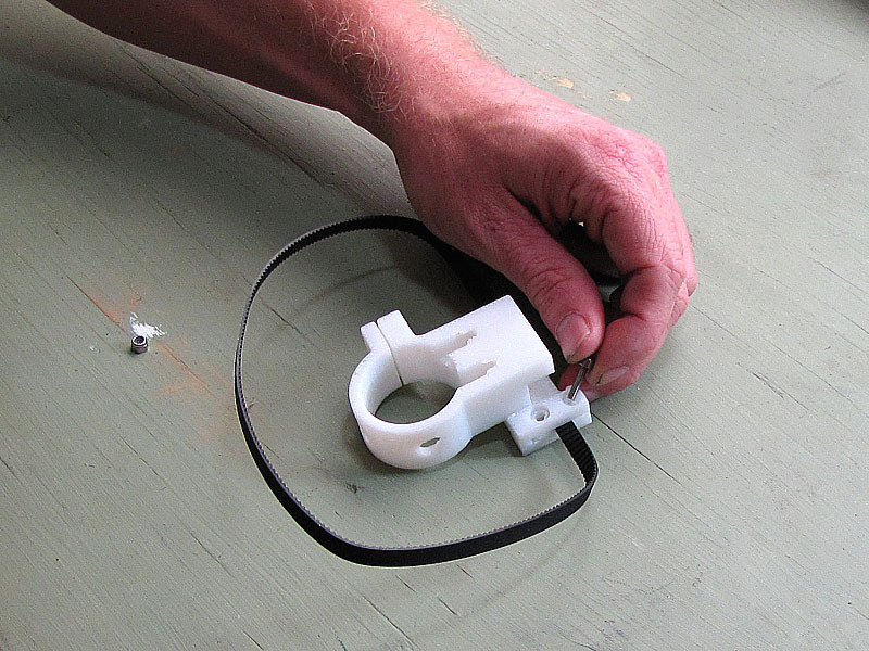
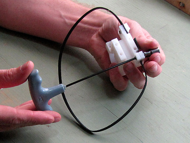
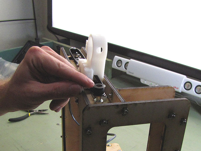
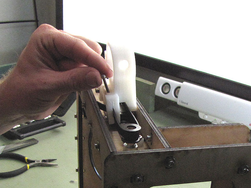
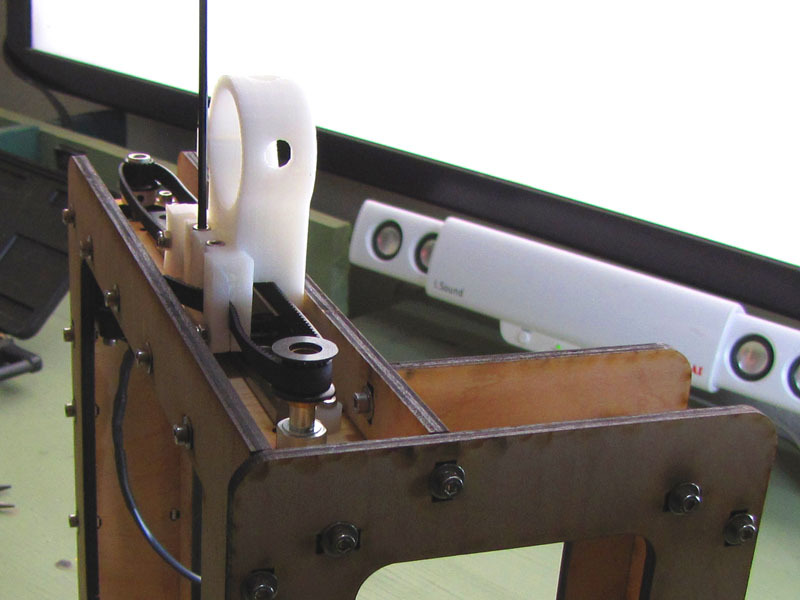
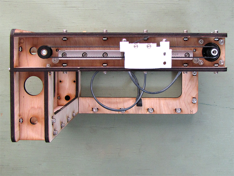
This part covers assembly of the X-axis systems, which is a straightforward process of bolting motor, idler pulley shaft, rail stops, and the linear rail itself to the frame assembled in Part 1. Then the X-axis timing belt is adjusted and installed as in Part II.

Project Steps

Install stepper motor

Orient the motor housing so that the side from which the cable exits faces the inside of the plywood frame.

Put the red rubber gasket over the motor shaft and align the four smaller holes, in the gasket, with the threaded holes in the motor case.

Pass the motor shaft, with attached drive pulley, through the large hole in part C from below. Align the bolt holes in the motor housing, the gasket, and part C.

Secure the motor with four M3 x 10 socket cap bolts and four M3 fender washers. Start all four bolts with your fingers, then tighten them down, in a criss-cross pattern, using a 2.5mm hex wrench.

If you have trouble fitting the motor into the frame, taking the gear pulley off the shaft temporarily might help with the tight fit.

Install idler pulley shaft

Pass the threaded end of the idler pulley shaft through the mounting hole in part C from above, as shown.

Reach under part C and start the 7/16″ hex nut on the threads of the idler pulley shaft with your fingers. The shaft is treated with thread-locking compound, so you may only be able to get just a thread or two by hand.

Secure the idler pulley shaft from above with a 1/2″ spanner, as shown, while tightening the hex nut from below with a 7/16″ socket, a small socket wrench, and a short extension. Don’t overtighten.

Install rail end stops

Pass each of two M3 x 16mm socket cap bolts through a 1/4″ white nylon spacer and into one of the rail-stop mounting holes at either end of part C.

Using your fingers, start a plain M3 hex nut onto each bolt on the underside of part C.

Once the hex nuts are started, use a loose 5.5mm socket, below, and a 2mm hex wrench, above, to tighten the rail-end stop bolts down securely.

Position and secure linear rail

As with the Y-axis linear rail, the X-axis linear rail is supplied with the bearing already installed, and two temporary green plastic rail stops in the outermost counterbores to keep the bearing from sliding off either end of the rail. Do not remove the temporary rail stops before the rail is secure between the permanent rail stops, or the bearing may come loose, in which case the bearing balls will spill out.

Set the linear rail in place over the mounting holes in part C.

Run an M3 X 12mm socket-cap bolt through each of two mounting holes in the rail and through the corresponding holes in part C. Exactly which two you choose doesn’t matter.

On the underside of part C, slip an M3 fender washer over each exposed bolt end, then use your fingers to start an M3 nylock on the bolt.

Using a 2.5mm hex wrench above, and a 5.5mm socket, wrench, and short extension below, securely tighten each bolt into its nylock.

Complete rail installation

With the rail secured by two bolts, it is safe to remove the temporary green plastic rail stops. Grasp them with long nose pliers and pull them out. Save them, in case you need to remove the rail later, for whatever reason.

Pass M3 x 12mm socket cap bolts through the remaining holes in the linear rail, from the top. You’ll have to slide the linear bearing around, a bit, to get to them all.

Secure each of the bolts from underneath with an M3 nylock and an M3 fender washer. Start them all with your fingers, then come back with a 5.5mm socket, wrench, and extension, below, and a 2.5mm hex wrench, above, to tighten them down.

Adjusting belt tension

Adjust the length of the belt as needed, and thread the loose end of the timing belt into the open clamp on the tensioner/motor mount assembly.

Insert each of two M3 x 12mm bolts through the holes in the tensioner clamp.

Start an M3 nylock on the exposed shaft of each bolt, then use a socket to grip each nylock while tightening the bolt with a 2.5mm hex wrench. Be especially careful, when working with fused-filament parts, not to overtighten.

Install belt

Make sure the belt tensioner is oriented as shown in the photograph, then slip the idler pulley into the timing belt and apply tension to the belt, as needed, to slip the idler pulley onto the idler pulley shaft.

Inspect the belt for correct tension. The rule of thumb is “when you slide the pulley back and forth, the belt should not bulge as it moves around the pulleys.” If the belt is too tight or too loose, adjust its tension, as needed, as described in the preceding step.

Slide the linear bearing, on the rail, until it is directly under the tensioner/motor mount.

Pass M3 x 20mm bolts through the four mounting holes in the tensioner/motor mount and into the threaded blind holes in the linear bearing. Tighten them down with a 2mm hex wrench, being careful not to damage the threads in the bearing. Work in a criss-cross pattern, and, as always, do not overtighten.

Conclusion

Up next: Building the Z-axis!