This is the fourth of eight guides in a series documenting my build of MakerGear’s Mosaic desktop FDM/FFF 3D printer kit.
- the frame
- the Y-axis
- the X-axis
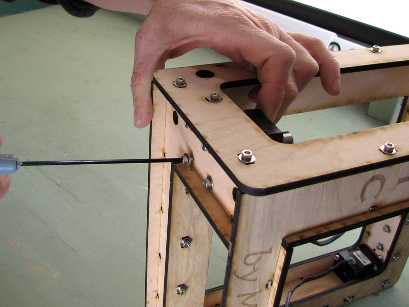
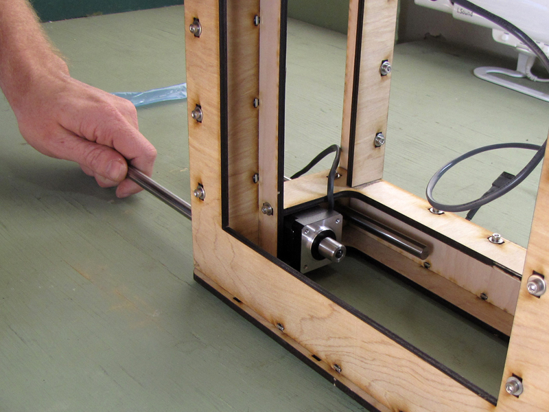
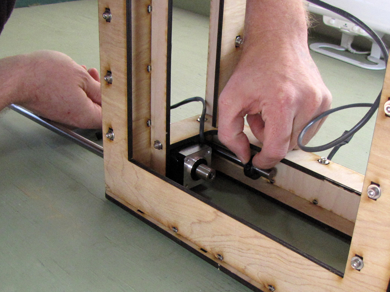
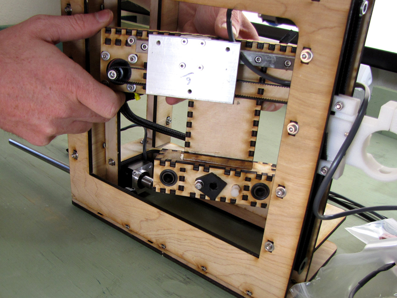
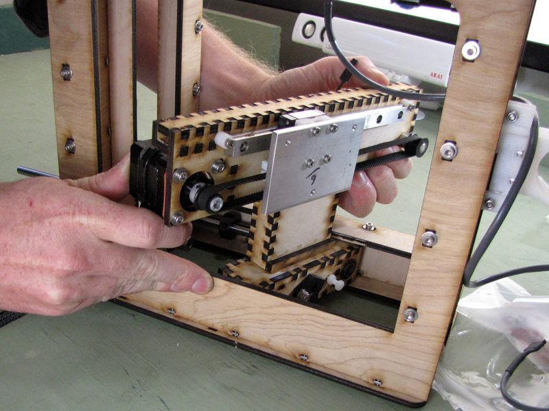
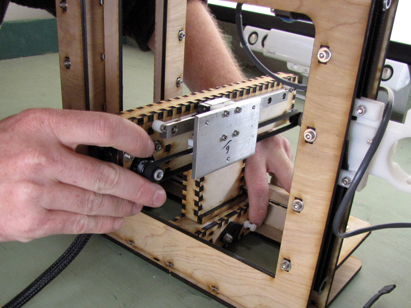
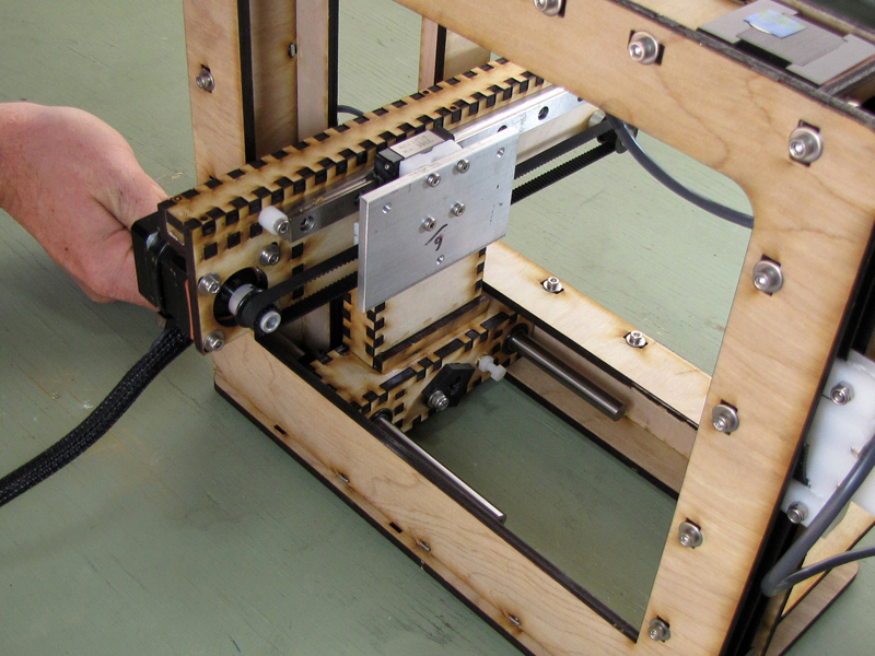
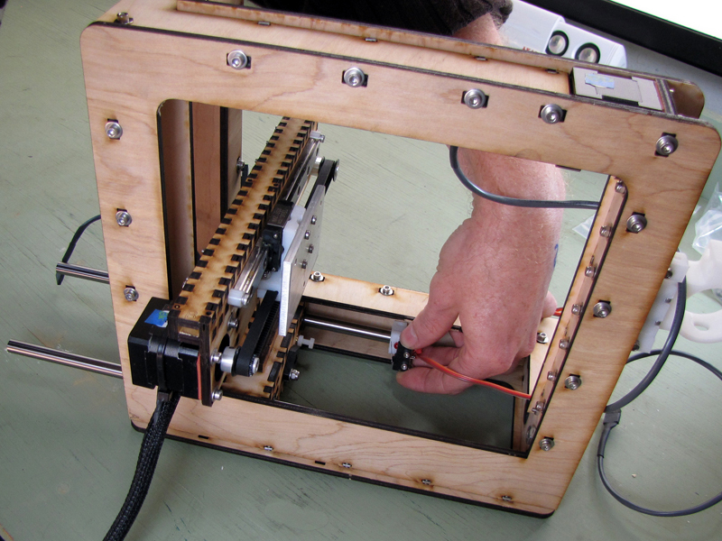
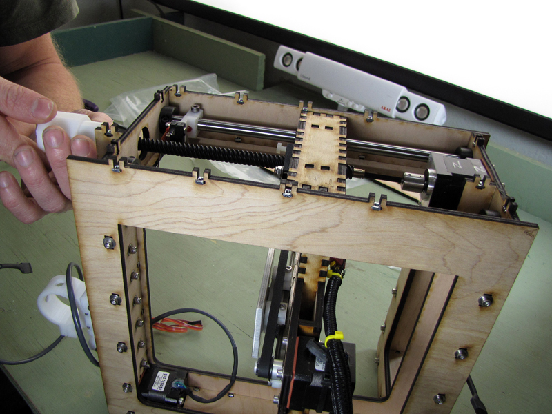
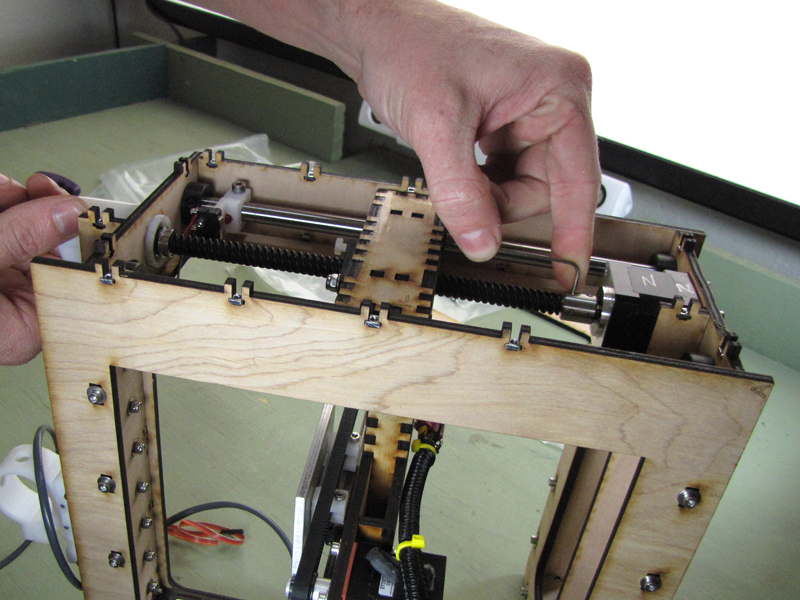
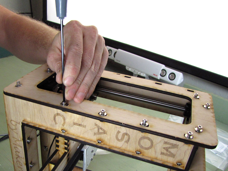
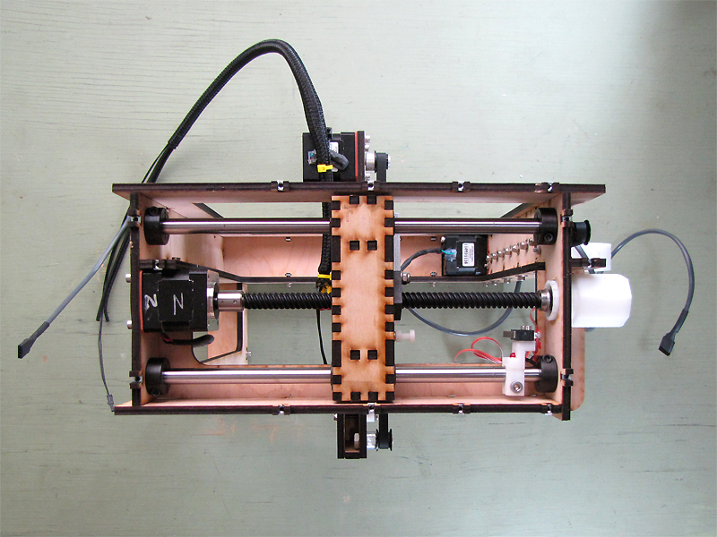
- the Z-axis
- the extruder
- the build platform
- the electronics
- the first print
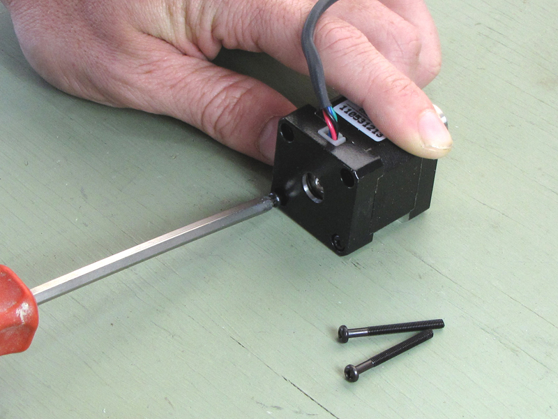
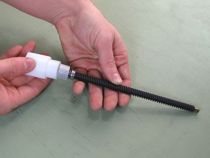
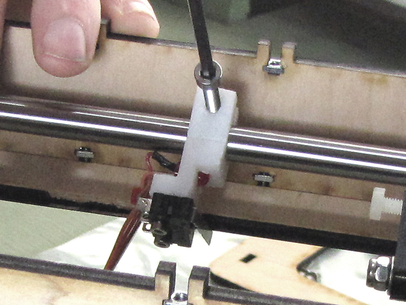
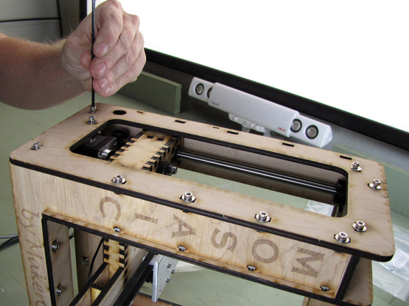
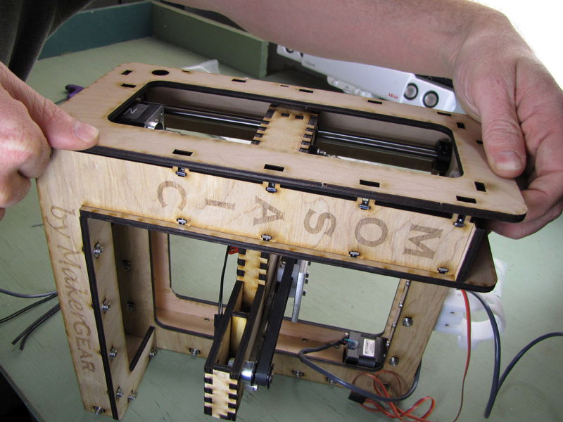
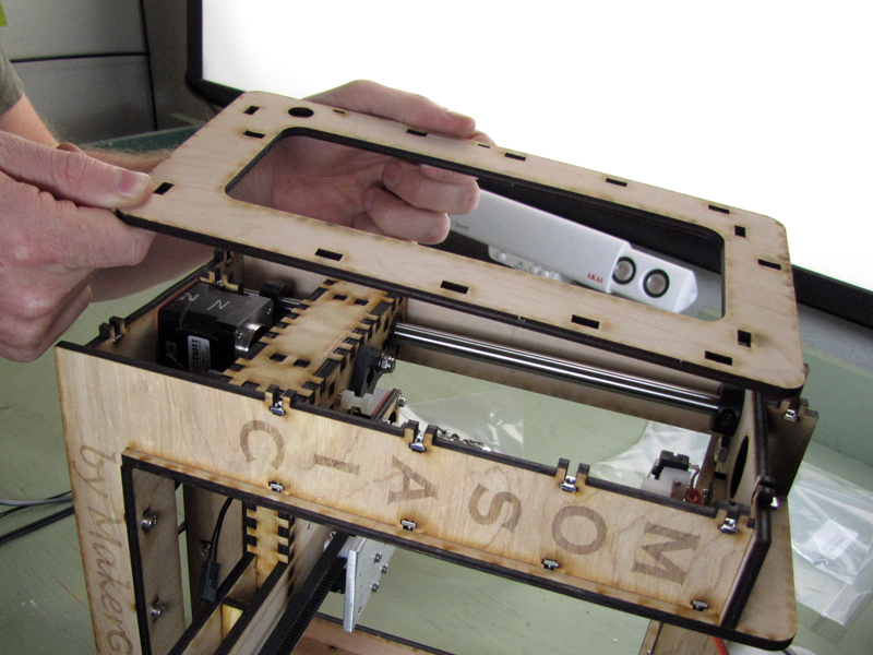
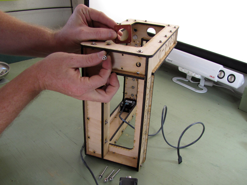
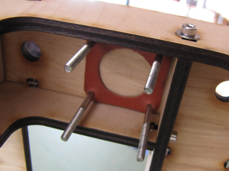
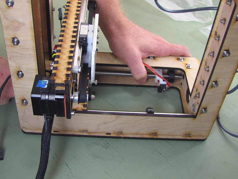
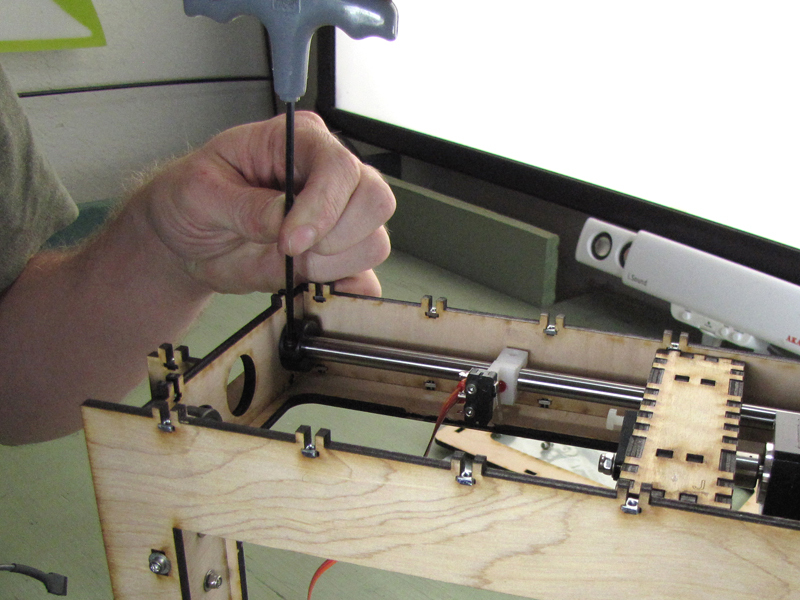
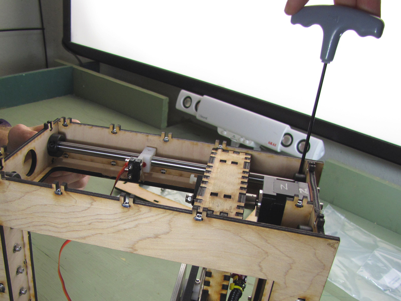
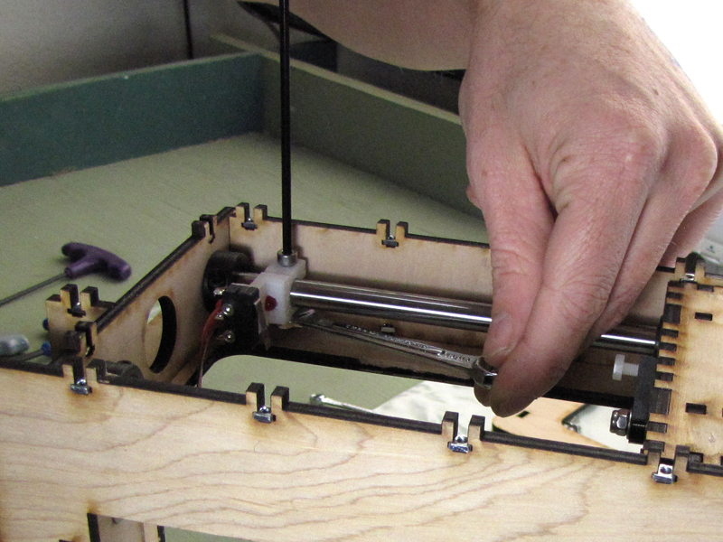
This part covers assembly of the Z-axis systems, including installation of the two hardened, precision ground steel shafts that guide the build platform along its vertical path of travel, the Teflon-coated lead screw that drives it, and the stepper motor that turns the lead screw. The Z-axis limit switch is also installed at this stage.