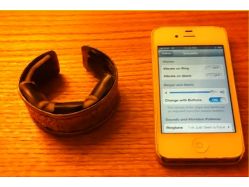
The goal of this project is to build a vibrating bracelet that alerts the wearer to incoming calls on an iPhone 4S. This device was originally created for a blind and partially hearing-impaired client who could not hear or see her phone ringing and wanted an inconspicuous and wearable device that physically alerted her of incoming calls to her phone.

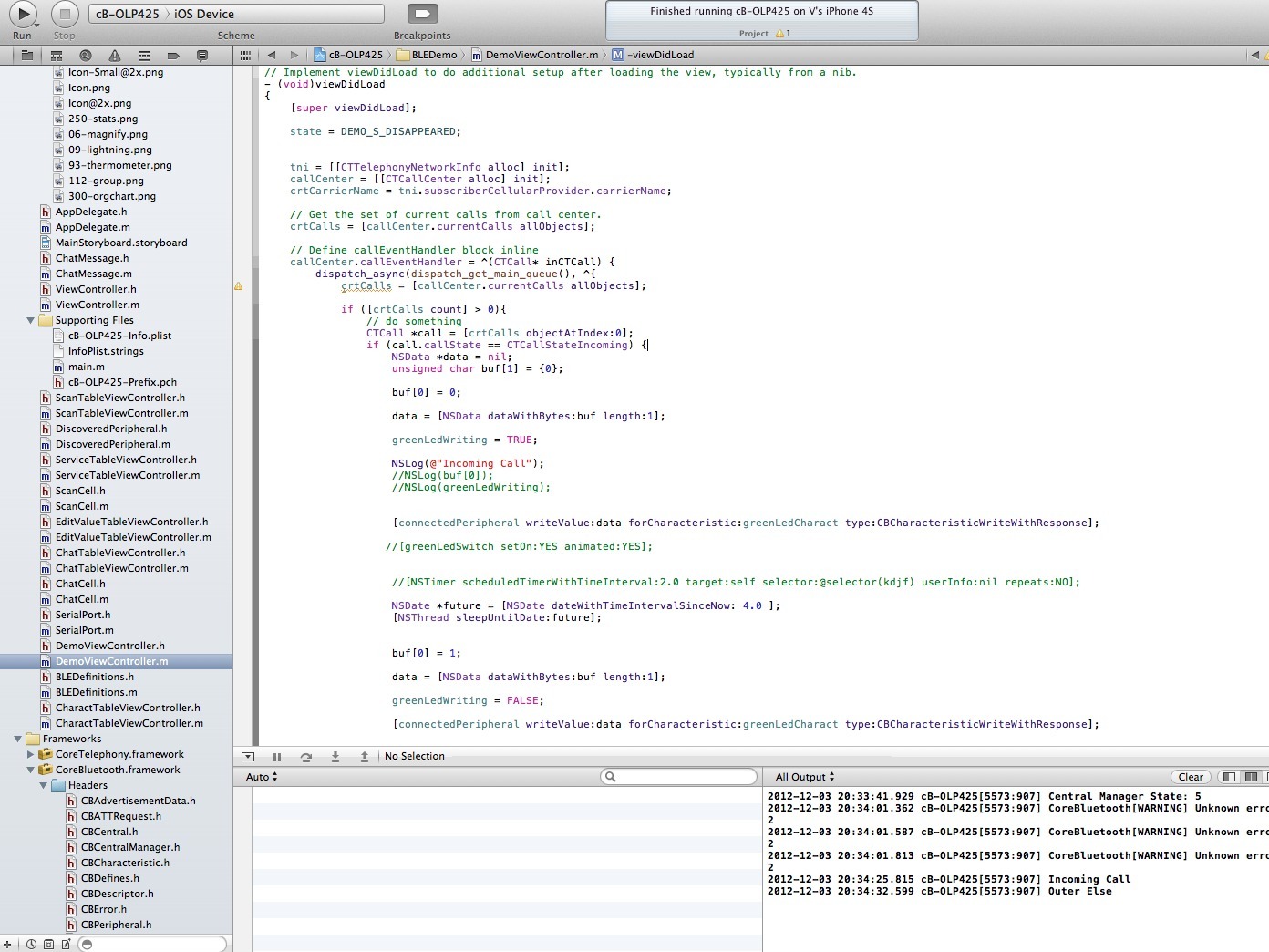
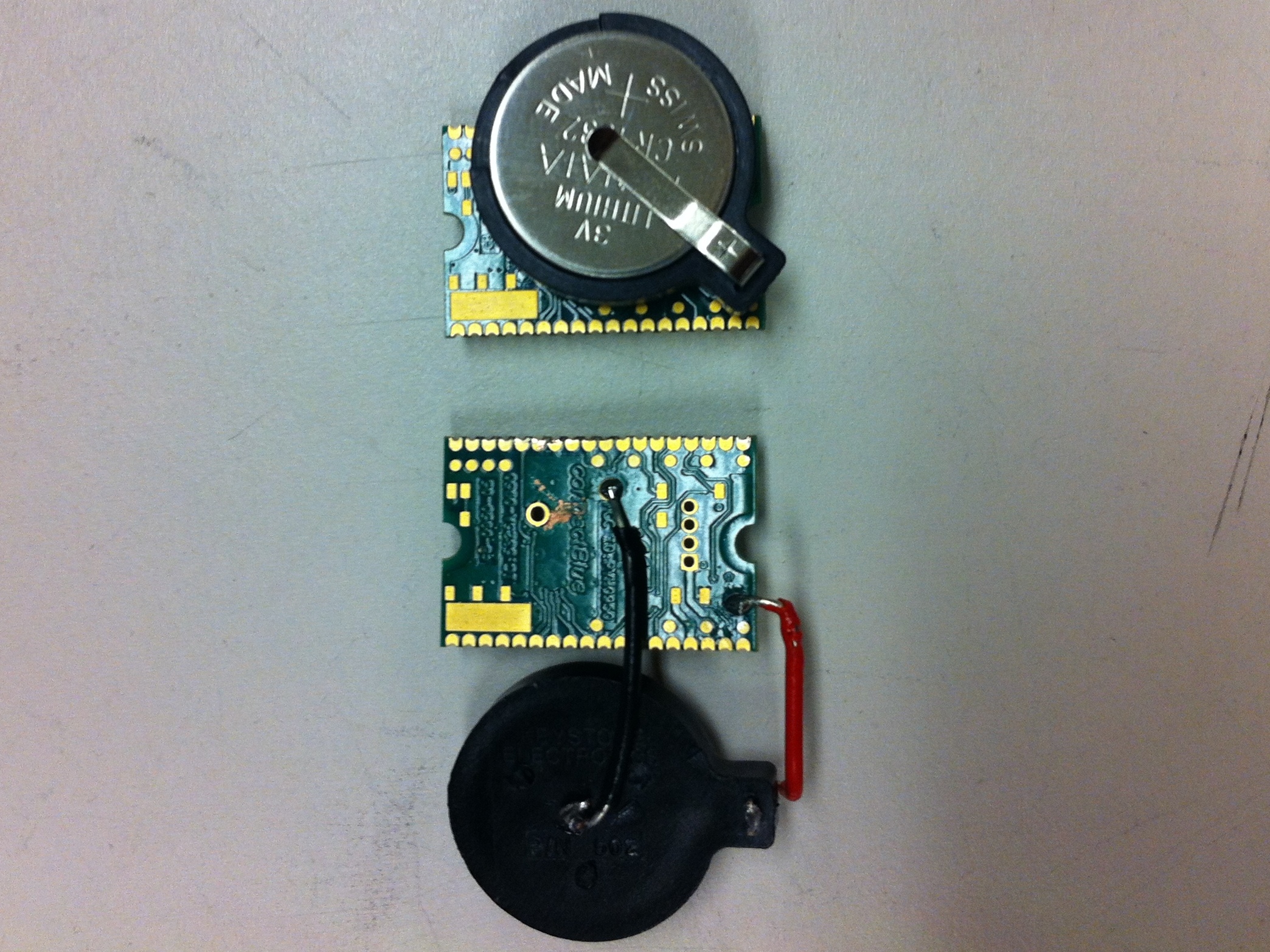
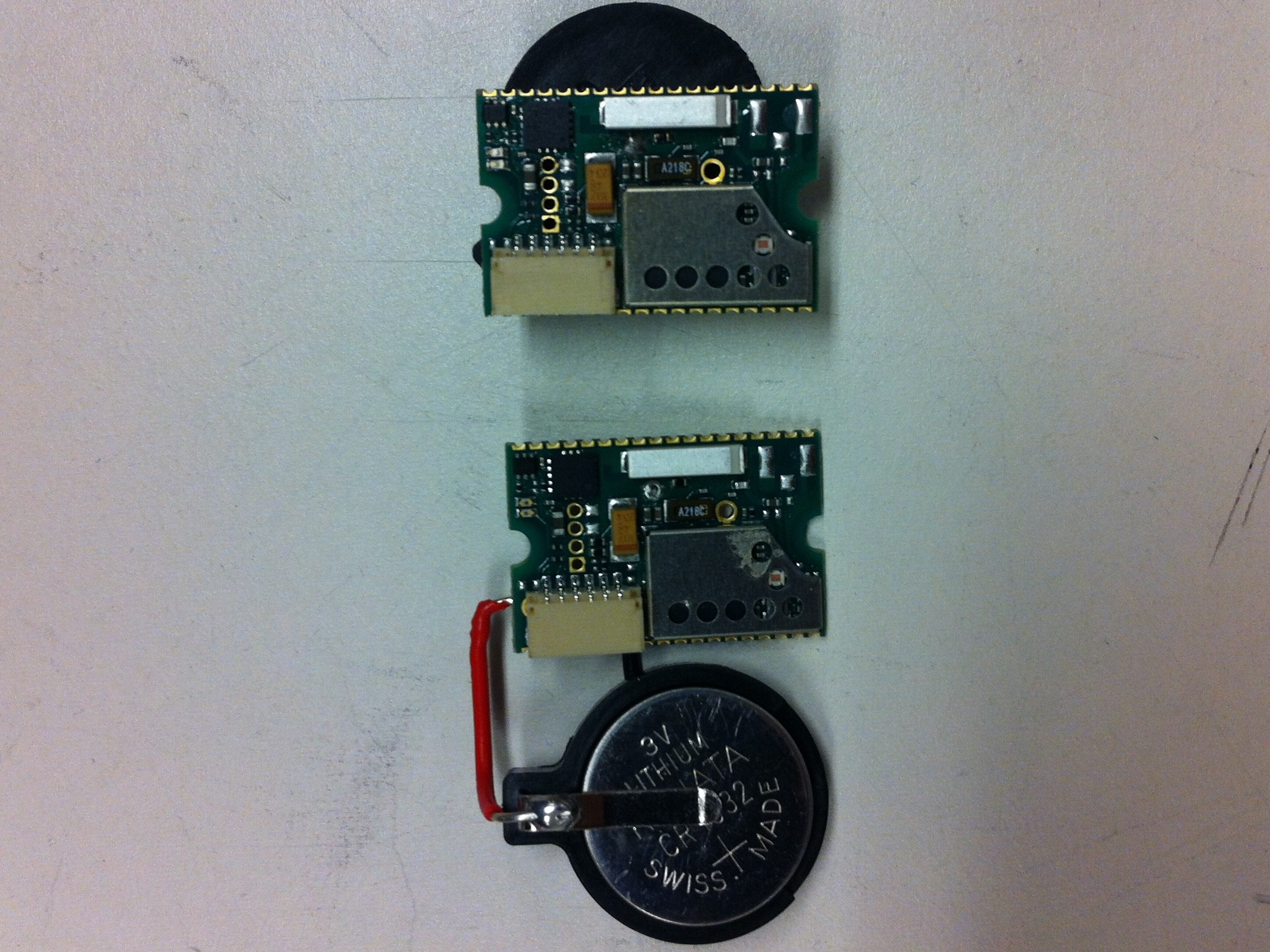
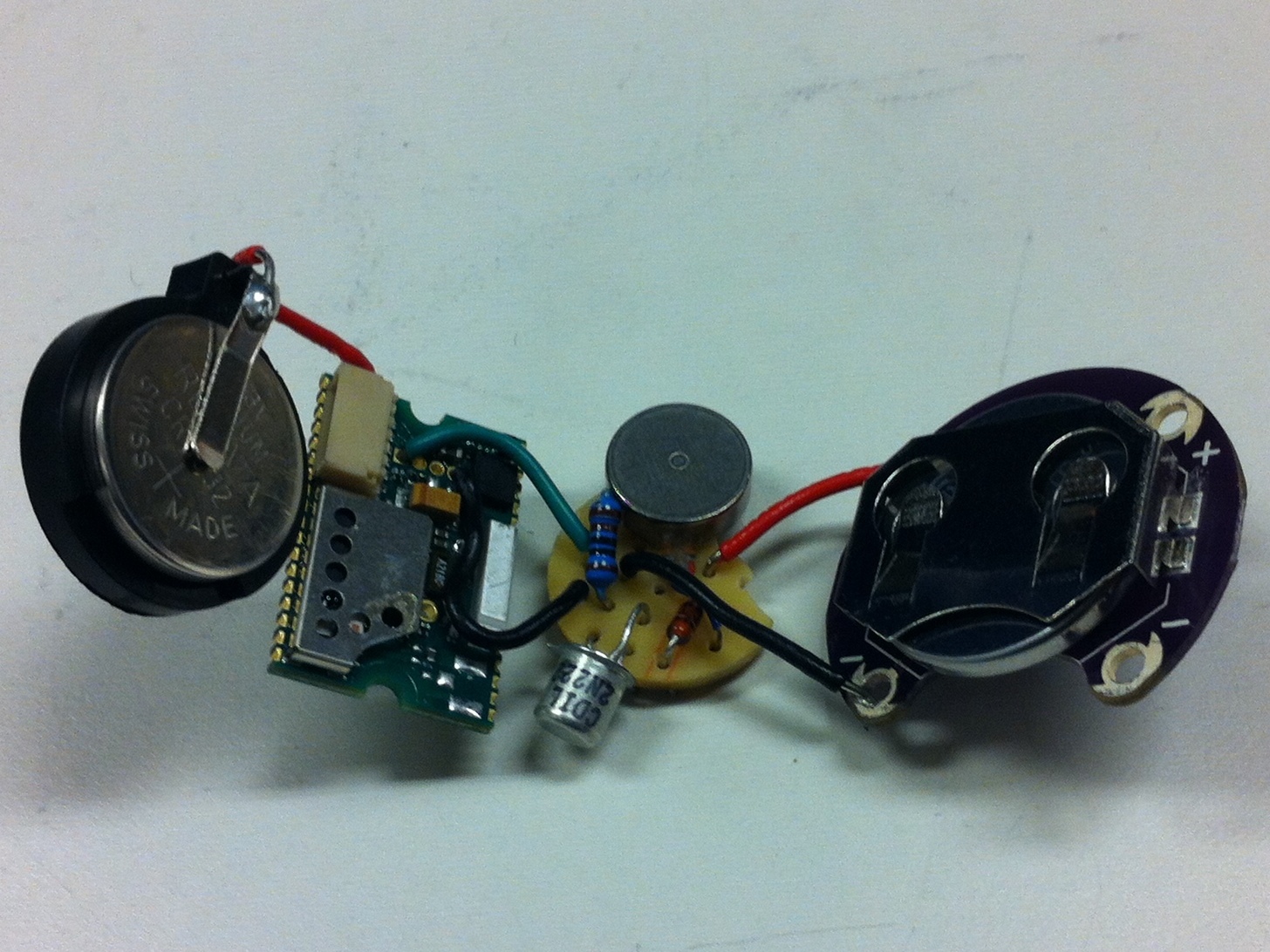
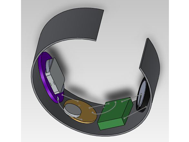
The bracelet contains a Bluetooth Low Energy module which pairs with the iPhone 4S through a specially designed app/Bluetooth profile. When the app detects an incoming call on the phone, a signal is sent to the Bluetooth which drives a vibration motor wired to the Bluetooth chip. The vibration is felt on the wrist of the wearer.

Project Steps

Install Apple Xcode and demo app

Download Apple Xcode and ConnectBlue demo app (contact ConnectBlue support team for OLP425 Demo App source code) onto a Mac.

Edit the demo app source code Apple Xcode.

Open OLP425 demo app project in Xcode.

Import CoreTelephony Framework under Linked Frameworks and Libraries.

Within DemoViewController.m, under -(void)viewDidLoad, enter the code that is shown in the image to the left. This code uses the CoreTelephony Framework to monitor for incoming calls and signals the Bluetooth to drive the vibrating motor for 4 seconds.

Add “Required background modes” key to Info.plist and add item “App communicates using CoreBluetooth” to the array.

On the main storyboard, edit the label above the green LED switch to say Motor.

Load app onto iPhone 4S.

Test the app by opening it and pairing with an OLP425. Call the phone. When there is an incoming call, the green LED on the Bluetooth should turn on for 4 seconds and then turn off. The LED simulates the action of the motor which will be connected in subsequent steps.

Modify the OLP425 Bluetooth module

Install IAR Embedded Workbench and TI Flash Programmer.

Download and open the OLP425 demo code zip file from here.

Edit the cb_led.c file to reassign the pin for the Green LED:

#define cbLED_PIN_GREEN (P1_4)

Edit the main.c file to configure the I/O pin:

//Configure P1_0 to output

P1DIR |= (1<<0);

Load modified program onto Bluetooth module

Under Project tab, select “Rebuild All” files on the IAR Workbench. This will save the edits into a .hex file to be loaded onto the Bluetooth.

Attach the OLP425 to the computer using the CC-Debugger cable.

Make sure to remove battery from Bluetooth before connecting to computer.

Open Flash Programmer and under Flash image, browse for the .hex file created for the revised demo code. Go to cb-0950 >> Exe >> .hex file with timestamp for when files were rebuilt.

Click “Perform Actions” and wait for the program to fully load onto the Bluetooth.

Build vibration motor circuit

Follow the circuit diagram (see picture) and build the circuit on a breadboard with output wires for ground (2 wires), power (1 wire), and motor driver input (1 wire) – black, red, and green respectively.

Test with two 3V power sources (either power supply or batteries) and make sure the motor vibrates.

Build the circuit on the PCB. Test again with two power sources.

Solder the circuit together on the PCB. Test again.

Make sure the two ground wires are connected together by solder on the back of the PCB!

Connect everything together

Cut the connections between the Bluetooth’s battery holder and the Bluetooth. Make a note of which pads on the Bluetooth the battery holder was connected to. Make sure the Bluetooth and battery holder are on the same plane.

Solder a black wire connecting the anode (on bottom of holder) and the anode pad on the Bluetooth. Then solder a red wire connecting the cathode (on side of holder) to the cathode pad on the Bluetooth.

Solder the motor driver wire (green in picture) to I/O pin 1 on the Bluetooth (the only pin with a square pad). Solder one ground wire (black in picture) to pin 4 on the Bluetooth.

The two ground wires should be connected by solder on the back of the PCB already so it does not matter which ground wire goes to which component.

Solder the motor power wire (red in picture) to a positive through-hole on the Lilypad battery holder. Solder the other ground wire (black in picture) to a negative through-hole on the battery holder.

Do a sanity check to see that the motor vibrates properly!

Open the app on the phone and pair with the Bluetooth device.

Call the phone and check to see that the motor vibrates for 4 seconds and then stops when the call is incoming.

The default state of the motor is ON by virtue of the way the I/O pins are configured. Thus, when the batteries are inserted, the motor will start vibrating until turned off on the iPhone app. The motor will then stay off as default until a call is received or the button on the app is pressed.

The Motor switch on the app interface displays ON when the motor is actually OFF, again due to the I/O pin configuration. Please excuse this bug. :)

Case the hardware into a stylish bracelet!

Tape the hardware with electrical tape so that all wires are protected.

Tape the hardware onto a piece of felt, precut to fit the underside of the bracelet.

Cover the hardware with felt so that felt lines the underside of the bracelet where there will be contact with the user’s skin.

Leave two flaps (to be secured with velcro or other such fastening device) above the battery holders for ease of battery replacement.

Attach the felt-encased hardware to the underside of the bracelet with strong glue/adhesive.

Be creative! If you have better ideas for casing and securing the hardware, try it out!