


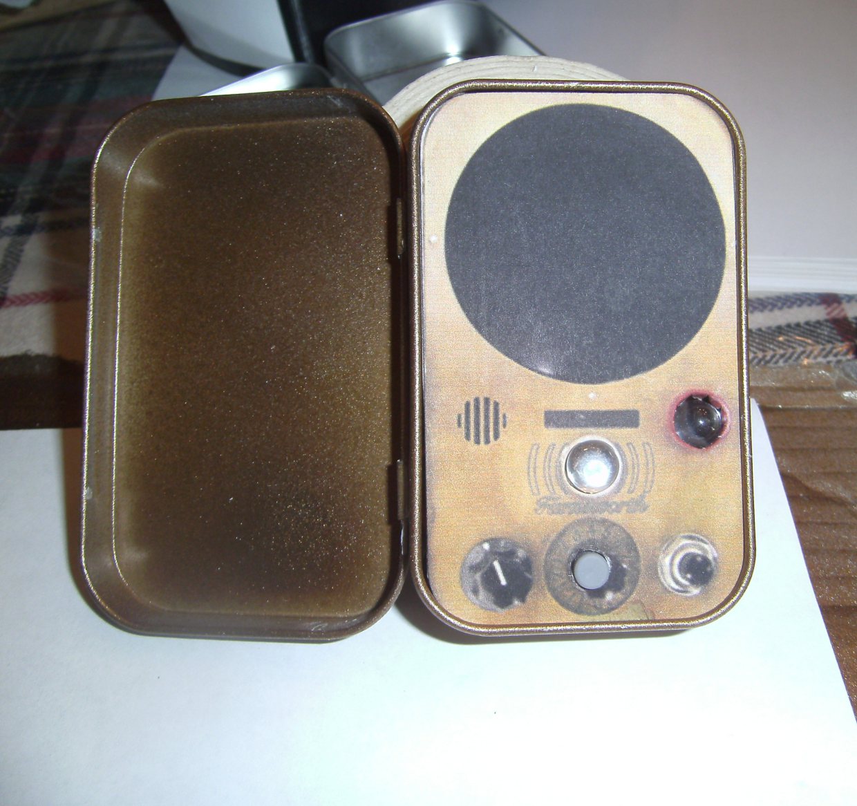

Photo: Andrew Terranova
If you are a fan of Warehouse 13, you are familiar with the Farnsworth device that the characters use to communicate. It is named after real-life inventor of the first fully electronic television, Philo Farnsworth. There are many examples of replicas for the Farnsworth by movie FX hobbyists that require machine shop tools or laser cutters to make. This is not one of those.
This is a miniature version of the Farnsworth. It is cheap, fairly easy to build, and will in no way pass for the actual device. However, if you are looking for an easy build with fun results, you may like to try it.
You can see it in action in the video below.

Want to give it a try? Just follow the steps and you’ll be calling up your favorite Warehouse agent in no time.