Water Bath Thermostat

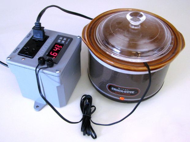
This project was inspired by Cooking for Geeks author Jeff Potter’s quick DIY sous-vide hack. My plan, initially, was to just hack the controller into an enclosure with an A/C outlet, the idea being that you could just plug any heater you wanted into the outlet.

Looking around for cheap temperature controllers, however, I happened across the STC-1000 on eBay for $25. It’s not PID, but I was betting it would still be accurate enough for almost any practical purpose. And since the STC-1000 has both heating and cooling functions built-in, the logical next step seemed to be to split a single A/C outlet so that you could plug a heater or a cooler (or both) into it and use it for all kinds of stuff.

The STC-1000 will regulate at any temperature between the freezing and boiling points of water, which opens up potential applications in chemistry, aquaculture, zymurgy, hydroponics, cooking, etc., etc.

Project Steps

Prepare sensor jumper cable

Cut a 4″ length off the end of the STC-1000’s bundled temperature sensor cable, and separate and strip the cut wire ends.

Remove the ring terminals from the binding posts and bend each at a 90-degree angle using two pairs of pliers, as shown.

Twist the stripped wire through the holes on the bent up leg of each ring terminal, forming a strong mechanical bond before soldering.

Flux and solder the ring terminals to the ends of the cable.

Prepare A/C outlet

Break off the “ears” on the outlet mounts with a pair of pliers. They are scored for this purpose.

Also break off the metal connecting tabs on the bus bars on the sides of the outlet so that each socket can be controlled separately.

Remove the screws from the mounting flanges. They will not be used for this project.

“Decora” outlets have additional ears on the mounting flanges for the faceplate screws. Cut these off with large side-cutters and file the cut ends smooth.

Apply power connector template

Print the PDF template attached to this project onto an adhesive-backed mailing label.

Cut out just the power connector template, for now, and peel off the protective backing.

Apply the template to one of the two sides of the junction box that is without a mounting ear. Center the template vertically, and align it horizontally with the bottom edge of the box, about 1/4″ up.

Install C14 power port

Drill 3/16″ holes aligned to the inside corners of the template. Start by marking the indicated centers of the holes with a sharp punch, then drill starter holes with a 1/16″ bit.

Rotate the box 90 degrees, as shown, and clamp the mounting ears to the edge of the bench top with the drilled side facing out.

Thread the blade of your coping saw through one of the upper two holes. Assemble and tighten the saw.

Rotate the saw blade as necessary and cut out each of the four sides of the opening.

Test the power connector’s fit in the opening, and file the sides as needed to expand it.

Once the C14 port fits in the opening, use the mounting holes in its flanges as a template to drill two small holes in the side of the box. Install the C14 port mounting screws and tighten into hex nuts inside the enclosure.

Apply panel cutting template

Use a pair of scissors to cut around the outside edge of the panel template. Cut to remove the line.

Peel off the label backing.

Carefully align the template with the lip on the underside of the junction box lid and press it down.

Cut panel openings

Use a 3/16″ bit to drill twelve holes in the lid where indicated on the template.

Thread the blade of a coping saw through one of the corner holes and assemble and tighten the saw. Saw as necessary to connect the four corner holes in each panel opening. One of these openings will hold the A/C outlet. The other will hold the STC-1000.

Use a file to finish out the edges of the openings you just cut. Smooth out any rough spots and flatten each edge, being careful to keep the corners round. Test the component fit occasionally to figure out when you’re done.

Install A/C outlet

Fit the outlet into the upper opening. From the front side of the panel, insert the two retaining screws.

Holding the screws in place, turn the panel assembly over and set it on the bench. Add a split lock washer and a hex nut over each exposed screw end.

Tighten the screws with a flat screwdriver while holding the hex nuts with your fingers or a small wrench or socket. Tighten until the split washers are fully compressed, and no further.

Install binding posts

Remove all nuts and washers from the binding posts. Each post should have two hex nuts and two insulating washers. The washers are not needed for this project because the enclosure is plastic.

Insert the binding posts into the mounting holes from the front of the panel as shown.

Secure each binding post with a single hex nut tightened against the back side of the panel. A small socket may be helpful for this operation, as in the following step.

Install temperature sensor jumper

Slip the bent, soldered ring terminals at the end of the temperature sensor jumper cable you prepared in Step 1 over the binding post screws.

Add an additional hex nut to each binding post to secure the ring terminals in place.

Tighten the hex nuts down with a small socket, as shown.

Install switch-side A/C leads

Cut two lengths of copper wire about 4″ long, and strip the ends.

Insert the end of each length of wire into one of the two binding posts on the inward side of the A/C outlet.

Secure the leads in the A/C outlet by tightening the binding screws with a flat-head screwdriver, as shown.

Install STC-1000

Slip the STC-1000 in from the front of the panel until the bezel is flush with the surface.

Slip the orange plastic panel clips onto the guide rails on either side of the STC-1000.

Compress the clips against the panel face from the inside, securing the STC-1000 in place.

Prepare power harnesses

Strip about 3/4″ from each end of each of three 5″ lengths of white 18 AWG stranded copper wire.

Twist the stripped ends of all three wires together into a bundle.

Slip the bundle into a yellow crimp-on .25″ female disconnect, as shown. Crimp the connector in place with a crimp tool.

Slide a ~50mm length of 20mm heat shrink tubing over the end of the bundle, positioning it so that it overlaps the end of the disconnect by a bit.

Shrink the tubing in place over the flame from a cigarette lighter or a candle.

Cut the end of the tubing flush with the end of the disconnect. The result should be a fully-insulated connector.

Repeat this entire step using three 5″ lengths of black 18 AWG stranded copper wire.

Prepare ground lead

Strip about 3/4″ from each end of a 5″ length of green 18 AWG stranded wire.

Insert one end of the stripped wire into a red crimp-on 0.25″ female disconnect.

Crimp the connector.

Slip a ~50mm length of 10mm heat shrink tubing over the connector, as above, and shrink it using a lighter.

As above, trim the heat shrink flush with the end of the connector.

Connect sensor, switched leads

Insert the free ends of the temperature sensor cable into the appropriate terminal block on the back of the STC-1000. Secure the leads in place by tightening the screws with a small flat-head screwdriver.

Route the sensor cable around the back side of the STC-1000 housing, as shown, and secure with a piece of electrical tape. The idea is to keep the sensor leads well apart from the power leads when the case is closed.

Note, at this point, which of the two outlets will control cooling and which heating. Go ahead and mark them on the front of the panel now, if you like. (See step 17.)

Insert the free end of each of the switch-side A/C outlet leads from Step 10 into one of the two heating/cooling binding posts. Secure the leads in place with a small flat-head screwdriver.

Connect power harnesses and ground lead

Connect a “black” lead to the open side of each heating/cooling terminal block on the STC-1000. Connect the third “black” lead to either side of the STC-1000’s operating power terminal block.

Connect a “white” lead to the free bus of each A/C socket. Connect the third “white” lead to the open side of the STC-1000’s operating power terminal block.

Connect the free end of the “green” lead to the grounding post on the A/C outlet.

Final assembly

Hold the front panel in one hand, as shown, and with your free hand reach into the junction box and attach the female disconnects for the black and white power harnesses, and the ground lead, to the appropriate tabs on the C14 power jack. They should slip on with a bit of force. Careful not to bend the tabs.

Slip the gasket into place on the junction box lid, and lower the junction box lid onto the junction box body.

Secure the lid to the junction box body using the screws that came with it.

Finishing touches

Label the the heating and cooling outlets appropriately. I used black-on-clear labeling tape in a thermal label printer.

Connect the temperature sensor leads to the binding posts.

Plug in the C13 power cable.

Testing and use

Plug a small lamp into the heating socket.

Follow the manual procedure for adjusting the STC-1000 set point well above room temperature. The lamp should come on with a click.

Adjust the STC-1000 set point well below room temperature. The lamp should turn off.

Move the lamp to the cooling socket. It should illuminate.

Though I found my controller to be accurate within the advertised 1C margin, your mileage may vary. You should calibrate the STC-1000’s temperature reading against an accurate analog or digital thermometer. The STC-1000 includes a user-adjustable linear offset up to 10 degrees plus or minus.

Conclusion

Sous-vide eggs, which are cooked in the shell, are a great place to start experimenting with this controller. I find an hour at 65C gives an absolutely perfect soft-boiled egg.