wavecopter-improvements-4

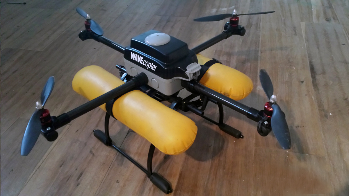
WAVEcopter is a fully waterproof quadcopter frame that I have constructed mostly from readily available and cheap electrical parts. My reasons for building it were to gain a new perspective on surfing photography, do aerial surveying of event sites, and to satisfy my general fascination with robotics and aviation.

I rebuilt the quadcopter after it suffered a serious collision into a cliff on the south coast of Cornwall, England. (I believe it was a pilot error after relying too much on a GPS fix and moving the quadcopter from its initial takeoff point.) Although this was a serious collision — full throttle into a granite cliff face at about 60 feet — all of the electronics and camera equipment was unscathed. This was testament to the ruggedness of the airframe; damage was limited to broken props, a cracked hub, and severed motor wires, all easily replaced for minimal cost.

The quadcopter is now on build 2 as I’m planning on replacing the Naza M flight controller with an Arducopter control board to enable mission planning with waypoints.

There are lots of different setups for quadcopter electronics, so I’ve skimmed over some of that detail as I think there are better setups than mine (like the Arducopter). The most important part of this project is being able to waterproof the frame while housing an optimum balance of battery power and weight.

The drone has made successful flights of over 10 minutes with no apparent overheating of speed controllers or motors, which was a big initial concern in a airtight/waterproof frame. I’m new to multirotors and I’ve read a lot about this, so it’s either a myth or I’ve been lucky so far. You can add heatsinks for the electronics on the underneath of the main housing if you’re overly concerned.

I hope you enjoy the project!

photo-eype-web

Project Steps

Prepare the hub.

Place the 4-way PVC intersection facedown inside the weatherproof electrical socket box. You’ll have to trim the ends with a hacksaw to ensure a snug fit.

Remove the hinged lid from the main box to make things easily accessible. Pop out the center lugs and make sure the 4-way intersection aligns with the holes. It should do perfectly.

You can see I cut out holes in the base of the box to attach heatsinks, but I ended up not using them in the next build as they didn’t seem to get hot.

Prepare the rotor arms.

Cut the 1000mm tube into 4 equal lengths of 250mm. I used a hacksaw.

Take all 4 conduit reducers and grind away the little lip you can feel on the inside, so it’s flush with the internal diametre. I just held them in my hand and used a Dremel with a drum sander attachment. Make sure you can now slide the carbon tube through the reducer. NOTE: You might find you have sanded too much — if so, use another reducer. The tube needs to slide through with a good push and no less.

Now lightly tap the reducer into the 25mm thread adapter until it stops. Unscrew the lock ring from the adapter and poke the threads through the main box, then screw the lock ring back on to form a tight connection. Do this for all 4 connections.

Now take the carbon tubes and push them/tap them with a rubber mallet through the thread adapters and into the 4-way hub as far as you can. Make sure each arm protrudes from the box an equal distance as the opposite arm (within 1mm–2mm).

Make the motor mounts.

Cut both ends off the 3-way inspection tees, as far back as you can. Make sure the cuts are square. Depending on your motors you might have to glue a tap (faucet) washer on top of the inspection cover to give the motor screws enough clearance. (I trashed a motor here by screwing into the windings, so be careful.) The washer also acts as a vibration cushion for the motor.

It’s very important to upgrade the screws that come with inspection cover as the motors will pull them free. I used some M4 machine bolts and just drove (forced!) them through the threads. It’s probably smarter to use smaller bolts (M3) with nuts.

Attach the rubber grommets to blank off the cuts you made earlier. This is a bit fiddly but they do fit, use a small flat-blade screwdriver to pry them in. They make an excellent seal once in.

Attach the motor mounts to your rotor arms by tapping slightly until they are level and tight. You may have some slight movement or twist on the mounts that may seem alarming but we can fix this later with some PVC pipe welding cement.

Make a hole in the inspection cover just big enough to thread the motor wires through. You can seal this later with Sugru.

Now that everything is fitting together and you’re happy — take it all apart, as you’re about to install the electronics.

Install the power electronics.

As there are many different ESC/motor/flight controller options out there, I will assume the reader has a basic understanding of how these are wired up. It’s pretty simple and you can see a typical setup here: http://code.google.com/p/arducopter/wiki/APM2RC

For the wiring harness of the 30A Naza ESC, measure the distance from the motor mounts to the center of the box and add 300mm. Cut your silicone wire and begin soldering the bullet connectors that you’ll use to connect the power distribution board. (You don’t have to use one of these boards, but I found it saved a lot of time.)

It’s a good idea to number or colour-code the ESCs at this stage because you’re going to be stuffing a lot of wires and you can easily get confused when you’re calibrating the flight controller. I used little coloured stickers for a reference.

Reattach your rotor arms and motor mounts and drill a 25mm hole on top of the 4-way hub. Thread the wires through the rotor arms — you’ll want about 150mm of cable to play with at either end of the arms.

Insert four 50mm M3 machine screws through the underside of the PDB (power distribution board) and secure on the topside with lock nuts. (These will form part of your standoff for the flight controller.) Attach the PDB where you drilled the 25mm hole, with the battery connectors facing the hinge of the lid. I used sticky velcro tape because I knew I might need to take it off. As you are attaching the power board, pull through the wires 3 at a time and attach a small cable tie.

You’ll have great fun now squeezing all this in and making it look tidy and safe! It’s worth adding some hot glue to the PDB connections as they are not very well insulated. Once you’re confident it’s all connected correctly, it’s time to install the flight controller.

Install the flight controller.

Cut out a scrap of plastic that will fit inside your box and support your flight controller (FC). Drill 4 holes in the plastic that will align with the machine screw standoffs on your PDB.

Attach your ESC control wires to the FC. Slide some 10mm round spacers onto to the machine screws on the PDB. Fix the FC to the plastic support (I used double-sided tape as indicated by DJI) and gently push it down onto the spacers, then attach lock nuts and screw them tight.

Prepare the batteries.

It’s very important to get the specified battery size that will fit under the lid of the box. Each battery’s dimensions are: 102mm × 37mm × 24mm.

I just used gaffer’s tape to bind the 2 batteries together and then used a XT60 harness battery splitter to wire them into the PDB.

Install the GPS puck.

Drill a 50mm hole in the centre of the hinged lid. Then glue the 63.5mm plastic dished head on the top of the lid with super glue or PVC pipe weld. Key the surface lightly with sandpaper to help the glue.

Install the GPS puck in the hole in the lid and secure it with strips of velcro tape. These will do double duty to secure the battery pack as well.

Install undercarriage and floats.

Prepare your undercarriage. The landing gear kit I bought had 2 trays that attach to the frame, where you can easily attach camera accessories, FPV kit, etc.

Now attach the floats. I used velcro straps to attach them to the undercarriage. Your installation may vary.

Flight check and calibration.

I won’t go into great detail here because there are many different flight controllers. Also, you’ll notice I only have a 6-channel TX/RX system and this isn’t ideal when using GPS and RTH functions on the Naza. I’ll be upgrading the drone to an Arducopter flight system in the near future and let you know how I get on.

If you’re using the DJI Naza M lite setup, you’ll find instructions online for calibrating the controller with your computer via USB: http://www.dji.com/product/naza-m-lite/download

One nice thing about the Naza is how perfectly snug the VU fits under the clip of the main box.

Install your motors, without props. As long as they’re brushless, which most are, then no waterproofing is necessary. It’s worthwhile spraying them after water takeoffs and landings with silicone spray to dry them out. (I’ve also heard great things about Liquipel; if you try it, let us know how it works for you, in the comments below.)

Connect the batteries and test all your flight control systems on the drone before attaching the props to the motors.

Final checks and sealing.

It’s now time to double-check that all seals are good. If any of the motor mounts or reducers are twisting in the frame, detach them and add a small amount of PVC weld to secure them.

Don’t add any PVC weld to the round 4-way junction box. If (and when) an arm breaks, you’ll easily be able to remove and replace that one arm rather than remove the entire hub.

Happy flying!