Whack-a-mole opener

Jim Chen designed an excellent electronic "Whack-a-Mole" game using 555 timers, LEDs, and bent-diode touch sensors, that you can build on a solderless breadboard; for a full explanation, check out his website here. This project is a more permanent version of Chen’s game, built on a custom PCB.

YouTube player

Check out more Weekend Projects.

Project Steps

Make the PCB

I used EagleCAD to lay out the circuit and PCB design for this project. Download and install the free version of Eagle CAD here: http://www.cadsoft.de/download.htm

Download the project design files here: (schematic and PCB). To make a board, you can either send the PCB files out to a fabrication house, or (if you’re feeling brave) etch your own board, as follows in this step.

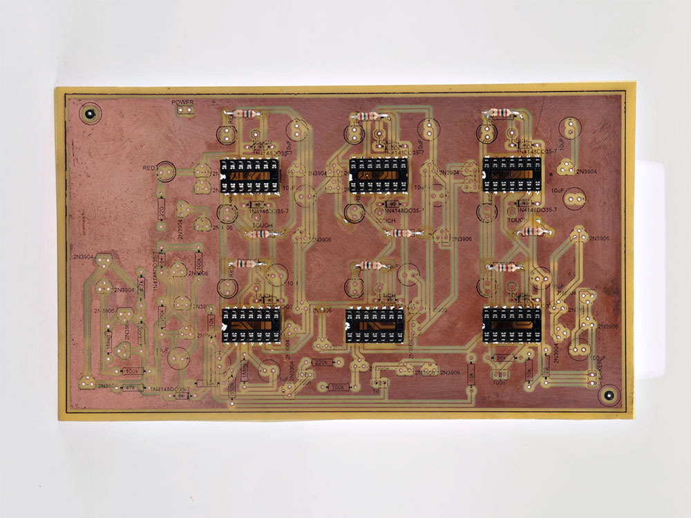
Launch EagleCAD and open the project design files, linked above. Print each PCB layout layer onto a transparency sheet. The CAD files are the best guide to component placement and orientation, so you will also refer to them later.

For each of the two layers, use the toner transfer method to transfer the etching mask to the copper cladding with an electric iron. Here’s a good page on the technique.

With the laser toner mask stuck tight onto the copper, etch the rest of the copper away with etching solution. Follow this guide: Cheap, Friendly, and Precise PCB Etching as a quick circuit board etching method, substituting etching solution for the peroxide, vinegar, and salt mixture described.

To make your circuit board double-sided, glue the two single-sided boards together back to back, using the two drill holes as an alignment reference. I used 3M #77 spray adhesive to bond the boards and left them in a press overnight.

Print out and iron the label layer onto the top of the board, using the toner transfer method. Finally, drill out all the board’s through-holes using a 0.75mm drill bit.

Add the Components

Connect all the vias on your etched board, the through-hole connections between the layers. Locate them by referring to the “vias” layer in EagleCAD. Lace each via hole with bare stripped solid wire, then solder the wire front and back, and trim.

Add six 14-pin chip holders. This is an optional step, but I prefer to install chips in sockets, for easy removal later.

The 556 chip contains two 555 timers, one on each side of the chip.

The EagleCAD files should make it fairly clear where to place all the components. Work slowly and methodically, and you should be fine.

Since this board does not have plated through-holes, be sure to place all components high on the board. This lets you solder the top and bottom sides of each.

Add the nine 150Ω resistors. (Brown-Green-Brown-Gold).

Add the 10μF capacitors. You can mix and match different capacitor values if needed (as I did) if you do not have 10 identical.

Add the nine red LEDs. LEDs are polarity-sensitive, so make sure to place them all with their flat edge facing “up” on the board (toward the top of the board when it’s oriented for you to read the printing).

Attach the 9 diodes – either 1N4148 or 1N914 diodes will work. These components are polarity-sensitive also, so they must be installed in the orientation shown here. Connect them with one wire lead (the cathode) looping high over the top, as shown — these wires will be our touch sensors.

Now it’s time to add the transistors. First up are the NPN type – I’ve painted these white to differentiate them from the PNP kind.

Warning: The PNP transistors I used, from a 15 pack, had a non-standard pinout that is backwards from that of most PNP transistors (check the picture). Be sure to confirm the correct transistor orientation for the circuit.

I unfortunately placed all the transistors according the orientation labeled in my CAD layout. This was wrong, so I had to pull them all out later, and reorient them with their flat sides facing opposite the way they are labelled on the PCB.

(I kept muttering “backwards, backwards, backwards…” while doing it (along with a few other choice words!! :-))

So if your transistors have their emitter and collector pins arranged the opposite way from the ones here, you will need to orient them the other way from these photos.

Add the remaining resistors as follows:

  • 220Ω Red-Red-Brown
  • 4.7kΩ Yellow-Violet-Red
  • 1MΩ Brown-Black-Green
  • 100KΩ Brown-Black-Yellow
  • 10KΩ Brown-Black-Orange
  • 150KΩ Brown-Green-Yellow
  • 220KΩ Red Red Yellow
  • 15KΩ Brown Green Orange
  • 56KΩ Green Blue Orange
  • 22Ω Red Red Black

Whew! Then after all of that, we can add the remaining 10μF, 1μF 0.1μF, 100μF capacitors, 2 diodes, battery pack, and the speaker.

(I almost forgot – pop the 556 chips into the sockets, too!)

Done! Give yourself a pat on the back if you’ve gotten this far; you deserve it!

Test Everything

“Testing, testing, 1, 2, 3…” You should now be able to connect the 5V power and switch it on.

All the lights should come on, and you should hear a “BUUUZZZZ!” sound, indicating the end of a game, from the speaker.

To start a new game, touch the touch sensors to clear all the LEDs. Try to turn off the LEDs as they randomly light up for as long as you can. If you take too long, the buzzer will sound and all of the lights will come on at once.

If things are not working correctly, check all the connections. Use a multimeter with a continuity function to confirm that all of the solder joints are healthy, and the connections are sound.

Note – in this picture the PNP transistors are oriented correctly.

Check out the YouTube video of our 555-Based Whack-A-Mole game in action.

Conclusion

In this age of the microprocessor, it's refreshing to see how one can implement a complex "program" using traditional analog circuits. Although this is not a beginner's project, it teaches some great fundamental circuit theory to those brave enough to take up the challenge of building it! In the process, you can also learn a handy electronics skill: etching your own circuit boards! If you do build it, we'd love to hear from you. Leave a comment!