Many of us over the years have collected boxes of CD cases of the music albums we purchases. Nowadays more and more people are buying digitally, but some of us still prefer the higher quality audio and tangible cover art of physical CDs (used CDs are often cheaper than digital downloads too). However, storing CDs in boxes, especially with their often beautiful album art, seems just wrong. This project is my attempt to remedy that.

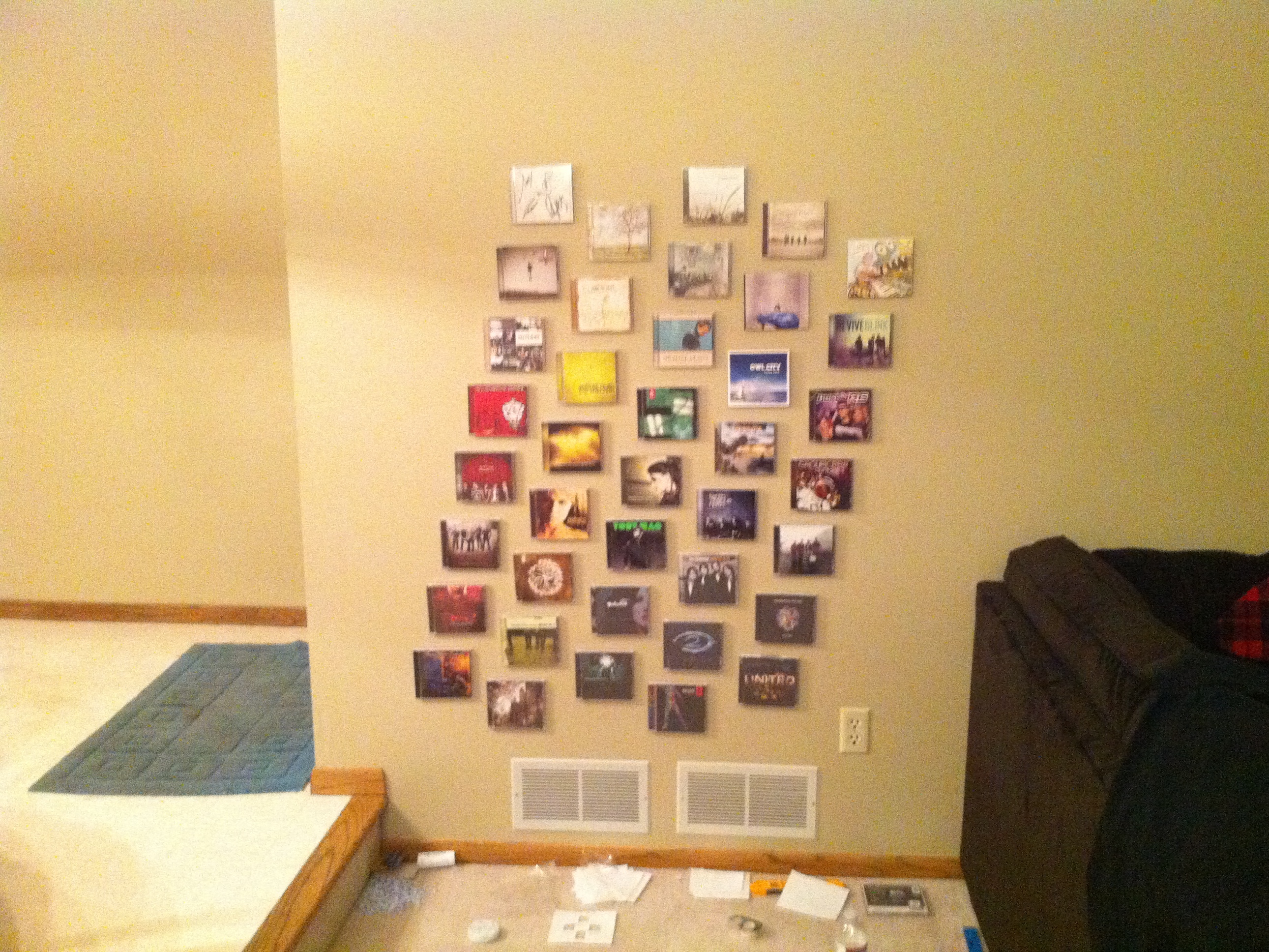
Logically this can be broken down into two parts: the artsy part and the geeky part. The artsy part is simply mounting your CD cases onto a wall in your house in a way that looks nice. The geeky part is making it so that touching a case makes music from that album start playing. You could just do the artsy part and still impress your friends, but the geeky part is how you’ll make their jaws drop.

To be as seamless and impressive as possible this project requires making permanent changes to a wall and access to the back of it. This is still possible without that, though you’ll need to create a frame of some sort yourself — if you do please send me a picture!

Provided you already have a computer and speakers, the whole thing should come in under $50.

Project Steps

Choose the music CD cases you want to use — I used 40 in this guide

Find a wall in your house where you want to mount them. For the interactive part you’ll also need access to the back of the wall (unless you want to get really creative and mount the cases onto a nice-looking frame)

Using a ruler and level, put a dot on the wall at the center of where you want each case

I decided to stagger the cases as shown in the picture — the centers of the columns are 7in apart and the rows are 6 3/8in apart (1.5in between cases)

Cut the velcro into ~0.8in squares and put 4 in a cross pattern around each dot on the wall (soft side) and on the back of each CD case (hook side)

The middle of each piece should be about 1.5in from the dot and from the center of the CD case

To speed things up I made a paper template the size of a CD case with holes where the velcro should be put (see pic)

The cheapest double-sided velcro I found was 3ft rolls at a local Michael’s arts store (see pic)

Take the keyboard apart and extract the circuit board from it

Keyboard circuit boards vary a lot — some are small, some are big, and some you can’t easily tap. You ideally want a small one that has easily-solderable contact points to the button matrix. I’d recommend buying a few for a few dollars each from a used computer parts store and using the best one. I used a Dell SK 8125.

Take your roll of wire and cut a bunch of 6in sections from it, stripping a quarter-inch of the ends of each

Solder one end of each wire onto the contact points on the circuit board for the button matrix (they’ll likely be in two groups, one bigger one and one smaller one, representing the rows and columns of the matrix)

Map the matrix. There are two groups of wires, one for the rows and one for the columns, and by touching various row/column combinations you’ll be able to emulate specific button presses.

Connect the keyboard to your computer

Run the program I’ve attached to this project; it’ll tell you which key is pressed

Touch one of the row wires to one of the column wires — if everything’s working the computer should tell you that a button was pressed

Record the ASCII code of which button was pressed along with which two wires generated it

Keep doing this for every combination — eventually you should have a piece of paper similar to the one shown in the pic

Clean the matrix. Keyboards have duplicates of certain keys — you can only use one of them (if End maps to both (1,1) and (4,7) for example, when it’s pressed the software sees End and doesn’t know which of the two coordinates it’s for). You also probably don’t want to use Num Lock, Caps Lock, or Scroll Lock, since they affect state. I put x’s next to them on my paper and then crossed out certain rows or columns that wouldn’t work.

See this ExtremeTech article for more details about keyboard matrixes and mapping them

Connect the wires you soldered onto the circuit board to a 25-pin DSUB connector

I’m a soldering newbie so I opted for a crimp-style connector instead of a solder one — your choice

For sanity’s sake I grouped the row wires together on one end of the connector and the column wires on the other

Form the circuit board and connector into box, to protect them and look mysterious

I used my old iPhone 3G box :p