


Have an idea you’d like to bring to market? In this series, John Teel walks through the process of scaling up from prototype to production. Follow each installment for a closer look at how to incorporate individual components.
The Global Positioning System (GPS) has to be one of the coolest technologies ever conceived of by humans. Although GPS has become commonplace because of smartphones it is still an amazingly advanced technology. However, for only a few dollars it’s possible to incorporate GPS into your new electronic product.
Introduction to GPS
GPS was developed by the US military in the late 70’s. The system consists of a minimum of 24 satellites in high orbit around the Earth. These satellites travel at nearly 9,000 miles per hour and orbit at an altitude of 12,000 miles. Each satellite carries an atomic clock with an accuracy of about 1 nanosecond. The satellites are distributed so that there is a line of sight to a minimum of 4 satellites from anywhere on Earth’s surface. The GPS receiver on the ground receives timing and location data from these satellites on a 1.575 GHz radio carrier signal.
The GPS receiver is able to then determine the distance to each satellite by timing how long it takes for the radio waves, which travel at light speed, to arrive at the receiver. By knowing the exact distance and location (encoded in the signal) of at least three satellites the receiver’s microprocessor is able to trilaterate its location. The fourth satellite is required as a redundant check and to provide timing corrections.
The term GPS actually refers only to the use of the satellite network operated by the United States. However, there are other navigation systems in operation such as Russia’s GLONASS network, China’s BeiDou network, Europe’s soon to be Galileo network, and Japan’s QZSS network. The term Global Navigation Satellite System (GNSS) is the more generic term that refers to any of the above systems.
Implementation
Implementation can be split into three types of solutions: full modules with an antenna, chip modules without an antenna, and discrete chip solutions. Table 1 below summarizes the advantages and disadvantages of each type of solution.

Table 1 – Comparison of GPS solution types
I always advise entrepreneurs to first focus on minimizing their development risks and costs even if that means a solution that doesn’t leave much, if any, profit. It is better to worry about maximizing profit after you’ve had some real market success.
All of these solutions interface with your product’s primary microcontroller via a serial UART interface. In most cases, they will output GPS coordinates in a standardized format known as NMEA (National Marine Electronics Association).
Full Module Solution
The simplest way to implement GPS is by using a full module that includes either a built-in antenna, or a connector for an external antenna. See Table 2 below for a comparison of four popular full GPS modules available.
| Full Module | GNSS | Discrete Chip | Sensitivity | Size (mm) |
| uBlox CAM-M8 | GPS, GLONASS, QZSS, BeiDou | uBlox | -167 dBm | 14 x 10 x 2 |
| AdaFruit Ultimate GPS | GPS, QZSS | MT3339 | -165 dBm | 35 x 26 x 7 |
| Telit SE868-A | GPS, GLONASS, QZSS, Galileo | SiRF Star V | -163 dBm | 11 x 11 x 6 |
| SparkFun GPS Module | GPS | Copernicus II | -160 dBm | 28 x 32 x 4 |
Table 2 – Comparison of full GPS modules (ordered from highest sensitivity to lowest)
Full modules offer the lowest development cost but the highest unit cost so they are usually only appropriate for early testing (or for DYI projects). The best solution for bringing a new product to market is to use a chip module.

Figure 1 – Adafruit Ultimate GPS full module with antenna connector
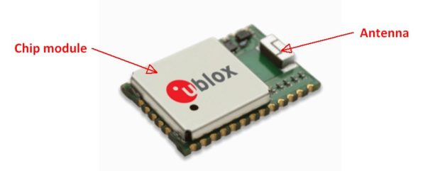
Chip Module Solutions
A chip module solution typically does not include a built-in antenna and usually requires at least a few external components. However, chip modules are much less risky than a discrete chip solution. See Table 3 for a comparison of eight chip modules currently available.

Figure 3 – GPS chip module from Wi2Wi
There are two types of FCC certification: non-intentional radiator, and intentional radiator. All electronic products require at least non-intentional radiator certification. Only products that wirelessly transmit require costly intentional radiator certification. Normally the only way to bypass intentional radiator FCC certification for a wireless product (that also transmits) is by using a pre-certified module. However, since GPS is a receive-only technology only the lower cost non-intentional certification is required. This means that using a GPS module doesn’t really save you anything on FCC certification.
| Chip Module | GNSS | Discrete Chip | Sensitivity | Size (mm) |
| uBlox M8 series | GPS, GLONASS, QZSS, BeiDou | uBlox | -167 dBm | 7 x 7 x 1 |
| GlobalTop Tech PA6H | GPS, QZSS | MT3339 | -165 dBm | 16 x 16 x 5 |
| SkyTraq Venus838FLPx | GPS, QZSS | Venus 816 | -165 dBm | 5 x 5 |
| Wi2Wi W2SG0021i | GPS, GLONASS, QZSS | SiRF Star V | -162 dBm | 7 x 7 x 2 |
| Maestro Wireless A2200-A
|
GPS | SiRF Star IV | -160 dBm | 14 x 10 x 3 |
| Linx Technologies F4 Series | GPS | SiRF Star IV | -160 dBm | 15 x 13 x 2 |
| Antenova M10478-A1 | GPS | SiRF Star IV | -160 dBm | 14 x 10 x 2 |
| Trimble Copernicus II | GPS | N/A | -160 dBm | 19 x 19 x 3 |
Table 3 – Comparison of chip module GPS solutions (ordered from highest sensitivity to lowest
One of the most important specifications for a GPS solution is its sensitivity (measured in dBm). This is because the signal being received is so incredibly weak. The GPS satellites have a transmission power of only 27W. By the time the signal travels 12,000 miles to reach your product on Earth it’s power is only about 3 x 10-16 W (-125dBm)! The sensitivity is even more critical for indoor operation where the signal strength may only be -155 dBm.
The greatest risk with a designing a solution using a GPS chip module is the antenna. This is true with any wireless technology but it’s especially true with GPS because of the weak signal power.
This means it’s critical for the antenna to transfer as much of this power to the GPS chip as possible. In order to achieve optimum power transfer you must match the impedance of the antenna, the transmission line connecting the antenna, and antenna pin on the GPS chip module. This impedance is almost always 50 ohms.
The impedance of the antenna and GPS chip transceiver are already set so you have to design the transmission line to match their 50 ohm impedance. I recommend using a free tool called AppCAD from Avago Technologes. On a PCB the type of transmission line used to connect an antenna is usually either a microstrip or a coplanar waveguide (see Figure 4).

Figure 4 – Microstrip versus Coplanar waveguide (from Avago Technologies AppCAD)
A microstrip is a type of transmission line fabricated on a PCB for carrying high frequency radio waves. It’s a conducting strip separated from a ground plane by a dielectric layer. A coplanar waveguide is similar except it is also surrounded by a ground plane. The 50 ohm impedance is from the transmission line to ground, and is not to be confused with the simple resistance of the line.
In addition to using a proper transmission line, it’s also necessary to add a pi-network (usually a C-L-C filter) between the antenna and the GPS chip. This allows fine tuning of the antenna impedance for optimum matching and maximum power transfer.
Discrete Chip Solution
Once your volume is high enough (100k+) you’ll want to begin finding ways to lower your unit costs and increase your profit margins. This is when it’s best to migrate to a discrete chip solution which can significantly reduce your product’s cost. A discrete chip solution has the highest development cost (and risk) but the lowest unit cost. Ideally you will be able to use the same discrete chip that was used on your initial module.
| Discrete Chip | GNSS | Sensitivity |
| CSR SiRF Star IV | GPS | -160 dBm |
| CSR SiRF Star V | GPS, GLONASS, QZSS | -162 dBm |
| MediaTek MT3339 | GPS, QZSS | -165 dBm |
| SkyTraq Venus 816 | GPS, QZSS | -165 dBm |
Table 4 – Comparison of discrete GPS chips
Conclusion
In most cases, it is best to start off with a full module GPS solution for initial testing. Then upgrade to a chip module to use for low volume market testing purposes. Once you’ve reached high manufacturing volumes then you can develop a discrete chip solution to lower your product’s cost. Remember to always start with the lowest risk solution. This advice is true in general when it comes to product development on a limited budget.
ADVERTISEMENT
Join Make: Community Today


