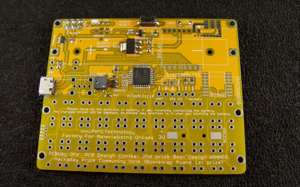
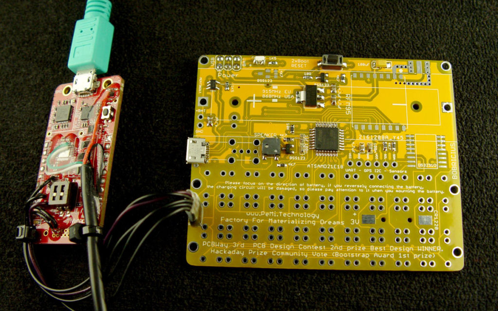
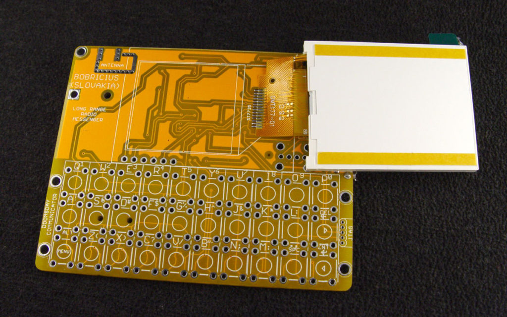
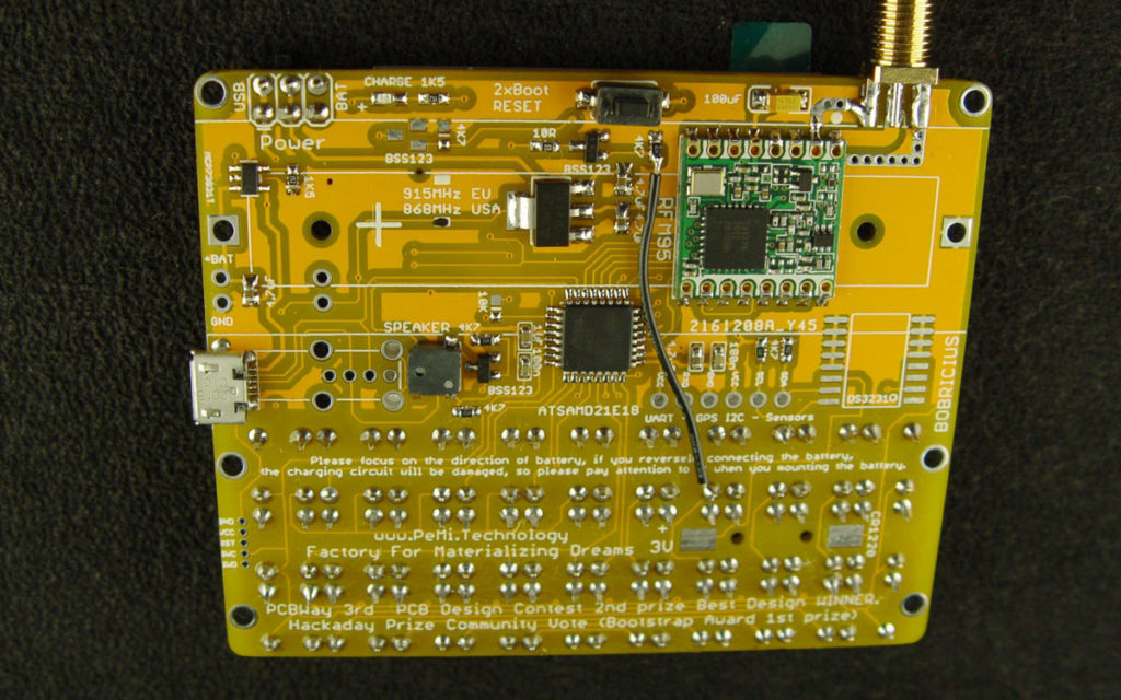
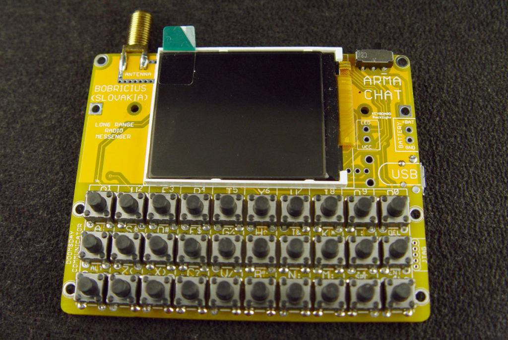
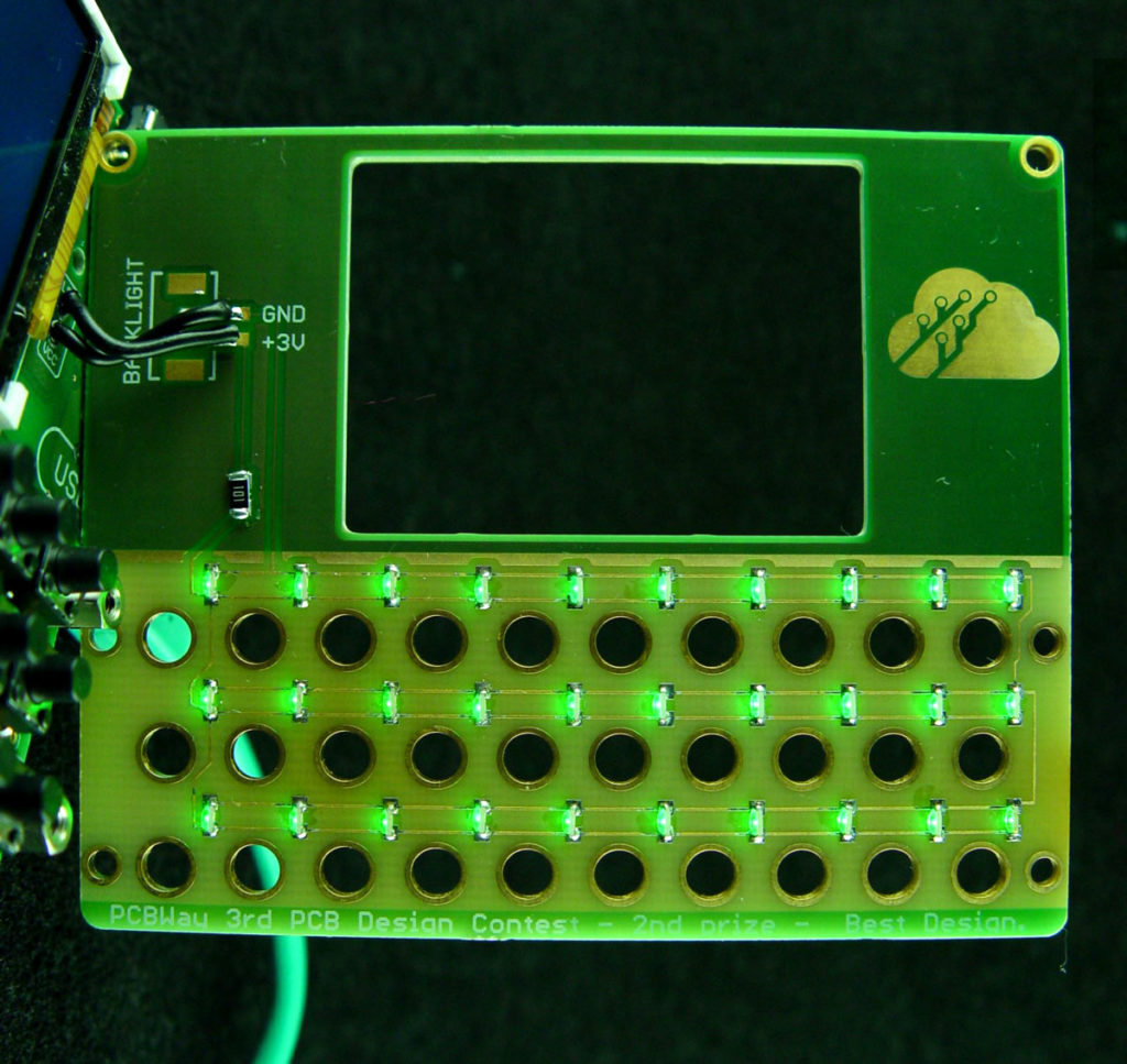
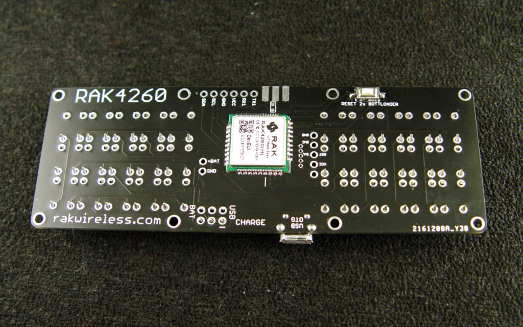
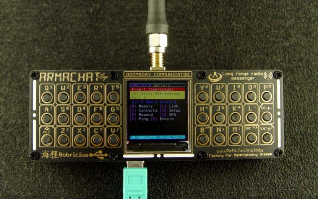
LoRa is great for long-distance sensor readings, but you can also use it for sending messages. This is my LoRa-based interpersonal communicator, called Armachat. I made it as a learning exercise to create a PCB with wireless communications and graphic displays. The device is a battery-powered, super high-tech, text-based walkie-talkie with an extremely simple and low component count (around 25 parts). I focused on using an SAMD21E18 microcontroller in an easy-to-solder TQFP32 package (same size as the popular ATmega328). Unfortunately this MCU is sold blank and needs a special Atmel-ICE device to program the bootloader — this is the hardest part of this project. Otherwise, no special manufacturing tools are required, it’s all on the PCB. The front panel can also carry optional backlight LEDs for the keyboard.

I originally called it an Armageddon communicator (hence “Armachat”) but I don’t think it would survive any imaginable disaster.

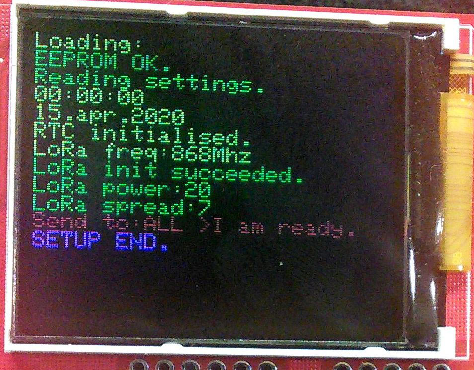
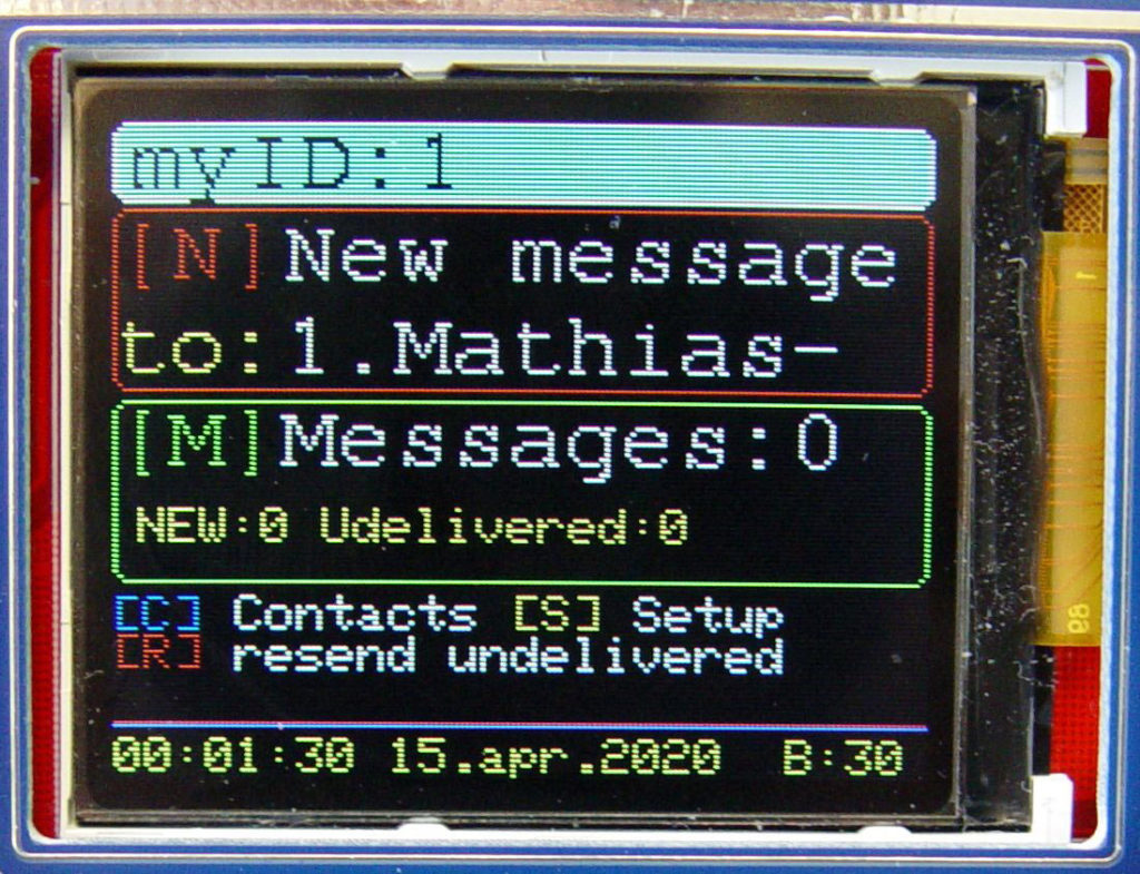
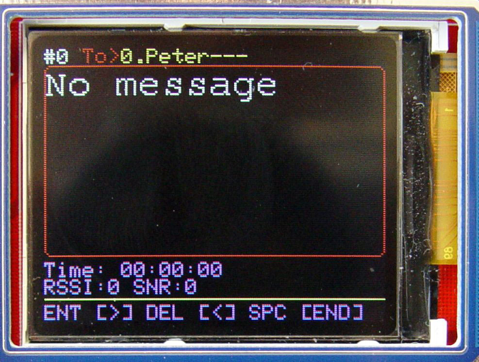
The software is not finished yet but at this point you can compose/store and send/receive messages with delivery confirmation, and resend undelivered messages from device to device with high potential to be received.

The newest revision, Ergo, features a split keyboard.

Why I Used the SAMD21E18

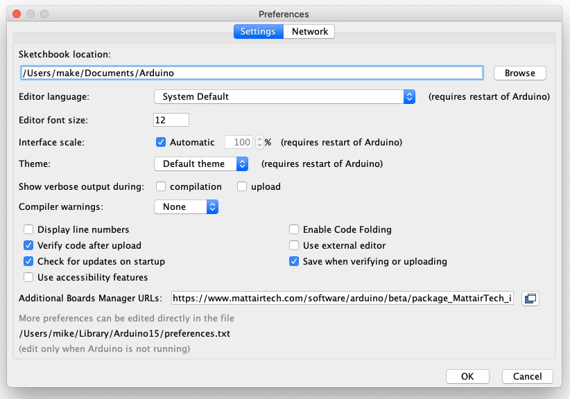
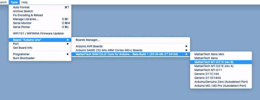
I chose this MCU for Armachat because it is Arduino compatible, low power, has native crystal-free USB, USB OTG, a lot of flash memory for updates, MSD bootloader from Adafruit, and you can easily update firmware just by dragging and dropping like a thumb drive. Plus, it’s cheap.

It’s also really low power; total Armachat consumption at full power with display on is 60mA — 20mA for the LoRa module, 20mA display backlit, 20mA MCU. I’m able to boot and send messages from Armachat just using power from a Stirling engine generator. You can see this on my YouTube page.

Other infrastructure-free communicators

  • Meshtastic: A GPS- and LoRa-based mesh communicator system which you can use standalone or access via your smartphone: meshtastic.org
  • Disaster.radio: This open source platform sets up solar-powered LoRa gateways that users can connect to via Wi-Fi to communicate off the grid. disaster.radio

Project Steps

Build It

The build is pretty straightforward; I’ve assembled 20 different prototypes just with hand soldering, and haven’t had any issues. 

Figure A

Solder the CPU and all active/passive components, following the labels on the PCB, except for the display, LoRa module, buttons, and SMA antenna connector (Figure A). 

Program the MCU

I am using the Arduino IDE and the Atmel-ICE programmer to write the bootloader into the SAMD21E18. 

Figure B

In the Arduino IDE menu bar, go to Arduino → Preferences → Additional Boards Manager URLsand add the following URL: https://www.mattairtech.com/software/arduino/beta/package_MattairTech_index.json (Figure B).

Figure C

Then in the Tools menu, select Boards Manager and install MattairTech. When installation finishes, go to Tools → Boards and select the board MattairTech MT-D21E (rev B) (Figure C).

Figure D

After you select that board, you’ll have some new fields to configure (Figure D). Choose:

  • Clock Source : INTERNAL_OSCILLATOR
  • Serial Config : ONE_UART_ONE_WIRE_TWO_SPI

Figure E

Now connect the Atmel-ICE programmer board with wires to the GND, VCC, SWC, SWD and RST pads on your Armachat board (Figure E). 

Back in the Tools menu, choose Programmer: Atmel-ICE. Then select Burn Bootloader. Now you can upload sketches to the device with USB.

Alternatively:

In Atmel Studio, write the special ARMABOOT.bin file, downloaded from my Github page. Then you can easily upload the firmware by dragging and dropping to your mass storage device. 

Upload the first firmware

If you have ARMABOOT.bin flashed, connect Armachat to your computer via USB. Double-press the RESET button for bootloader activation.

If you have a display connected, the backlight will start flashing (breathing).

Copy first.uf2 from my Github page to the newly displayed mass storage drive. Wait for it to finish writing, then press RESET again. If you hear a beep, the firmware is running. 

You can also create the UF2 firmware from scratch. Download the following libraries (or get them all from my Github page):

Plus the source code, located at github.com/bobricius/armachat. Compile and upload the code in the Arduino IDE.

Solder the last components

Figure F

Solder the display (Figure F), then power up the Armachat. If you see messages, it’s working. If the display is white, try pressing/holding the RESET button. If it’s not working, check the flex cable connection. Once the display is working, you can remove the tape backing and stick it to the main board. 

Figure G

Figure H

Next solder the RFM95 LoRa radio module, or the corresponding version for your region (Figure G). Power on the Armachat; if you see LoRa init succeeded, things are looking good (Figure H). If not, check the radio module connection. 

Figure I

Finally, solder the buttons and SMA antenna connector (Figure I). 

Front panel backlight (optional)

Figure J

This is optional. Solder in the backlit LEDs. I wanted perfect light spread so I used 30 LEDs, one for each button (Figure J). The front panel is then mounted with distance bolts and M2 screws.

Use It

Figure K

The communicator is controlled via shortcuts. From the main screen (Figure K) you can press:

Figure L

  • S: Setup To adjust communication frequency, LoRa transmission settings, and set your ID number from 0–10 (Figure L). 

Figure M

  • C: Contacts The address book allows 10 contacts (for now) with fixed names (Figure M).
    I’m working on new software that will let you choose your name, which will automatically update to your contacts’ address books. 
  • N: New message The keyboard buttons have multiple functions, switched with the Alt key. In “lowercase” mode, the Enter button sends the message; in other modes it works as the right arrow and Del is the left arrow. The Space button creates a space, period, or comma.

    After sending a message, Armachat waits for a delivery confirmation; if delivery is not confirmed, it stores the message into memory with an undelivered attribute. 

    Every unit sends an alive message when it powers on, and every unit that receives this message then resends any undelivered messages.

Figure N

  • M: Messages Read your new messages; and store sent/received/undelivered messages (Figure N).

    Software is now very basic but I’m intensively working on new features. There are almost no limits to routing, forwarding, mesh networking, and encryption. The device has lots of free flash memory and computing power.

Distance Tests

LoRa is known for its long-range capabilities. The maximum distances I’ve gotten with my communicator, through some small hills and houses in my village (not line-of-sight) at max
power, with spread factor 12:

  • 700m (about 0.43 miles) to gateway on my garden deck
  • 1,500m (almost a mile) to gateway in my window, about 4m (13′) above ground
  • 4,300m (2.67 miles) to gateway in attic window, 10m (33′) above ground

Of course this all depends on the antenna, obstacles, and radio settings.

Conclusion

Ultimately, this is a learning device to play with LoRa communication or to tinker with high-tech Arduino aspects. With it, I have furthered my skills in:

  • QWERTY keyboard reading 
  • Creating and displaying graphics 
  • User interfaces
  • Saving data to flash
  • Sending results over radio or USB 
  • Working with I2C sensors
  • Processing GPS data.
Figure O

I’m now working on two new Ergo boards with a split keyboard that’s easier to use: one with the same MCU and LoRa chips as this version, but with a 1.3" 240×240 ST7759 IPS display, and another with the RAK4260 module from rakwireless.com, which combines a Microchip ATSAMR34J18 SiP with LoRa capabilities on the chip (Figure O). This will really simplify the design; the board will only need the Li-ion charger, 3.3V regulator, and speaker. 

And finally, I’ve created a compact Nano (4×4cm) version without buttons — but it does include a USB host for a PC keyboard. I’m working to set it up as a miniature repeater/receiver as a future software update.