Laser Harp Synthesizer
Photo by Evan Reynolds.

I find laser harps fascinating. The first time I saw one was when I stumbled across a video of a guy using lasers to play the theme song to Tetris. I thought it was the coolest thing ever, but I couldn’t justify the cost of buying one. Instead, I decided that I’d try to build one myself.

After an online search I found that Make: ran an article on a DIY Laser Harp build back in 2012.

YouTube player

It was really helpful for understanding concepts, but I wasn’t really able to follow his plans or source some of the parts he used. On the other hand, it looked like a GREAT starter project for the new Arduino I’d just purchased! So, I built my own from scratch.

Conceptually it’s very similar to Ruete’s 2012 design on Make: but with one big addition — I wanted the octave of each note to change when I moved my hand up and down the beam.

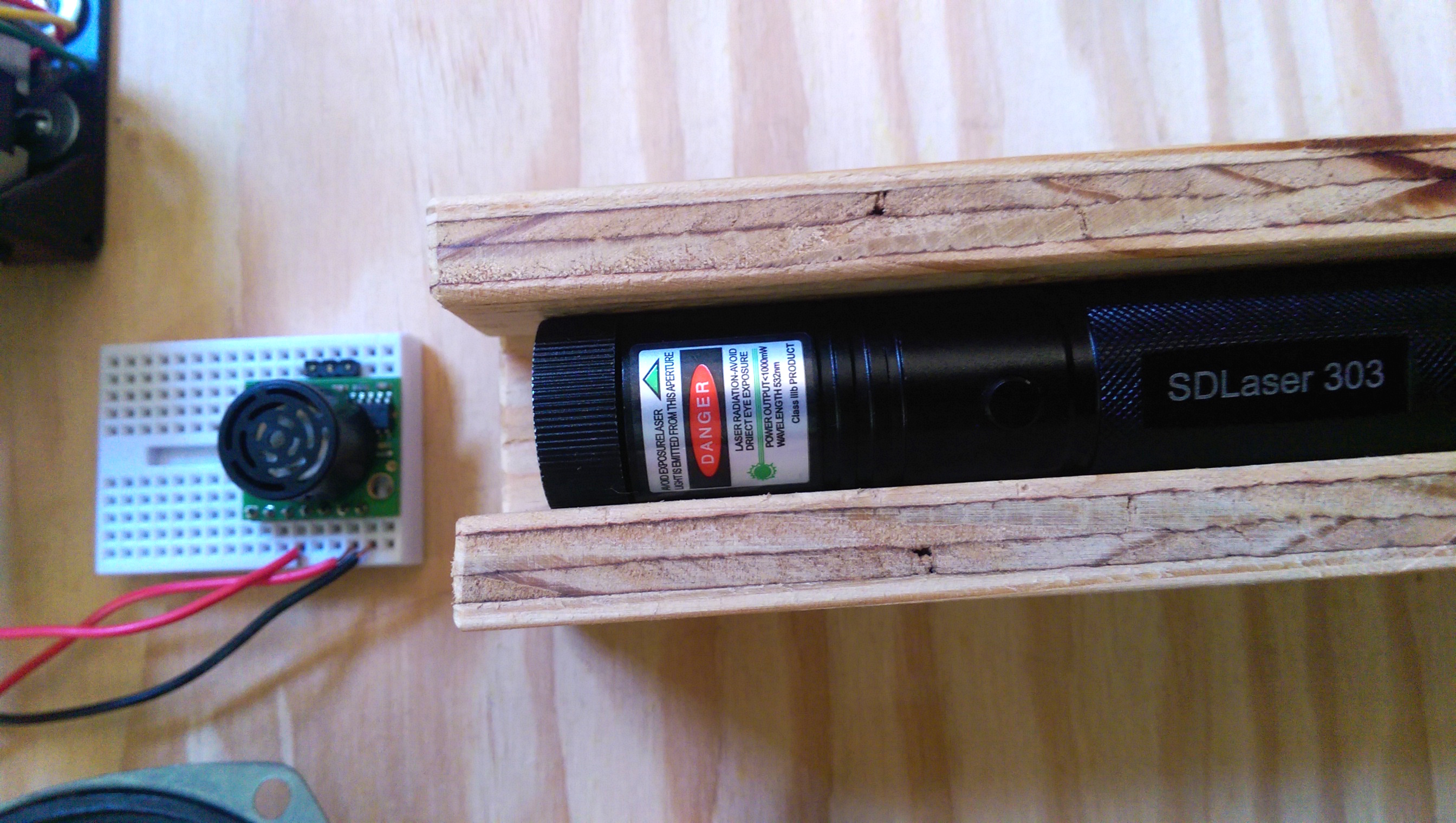
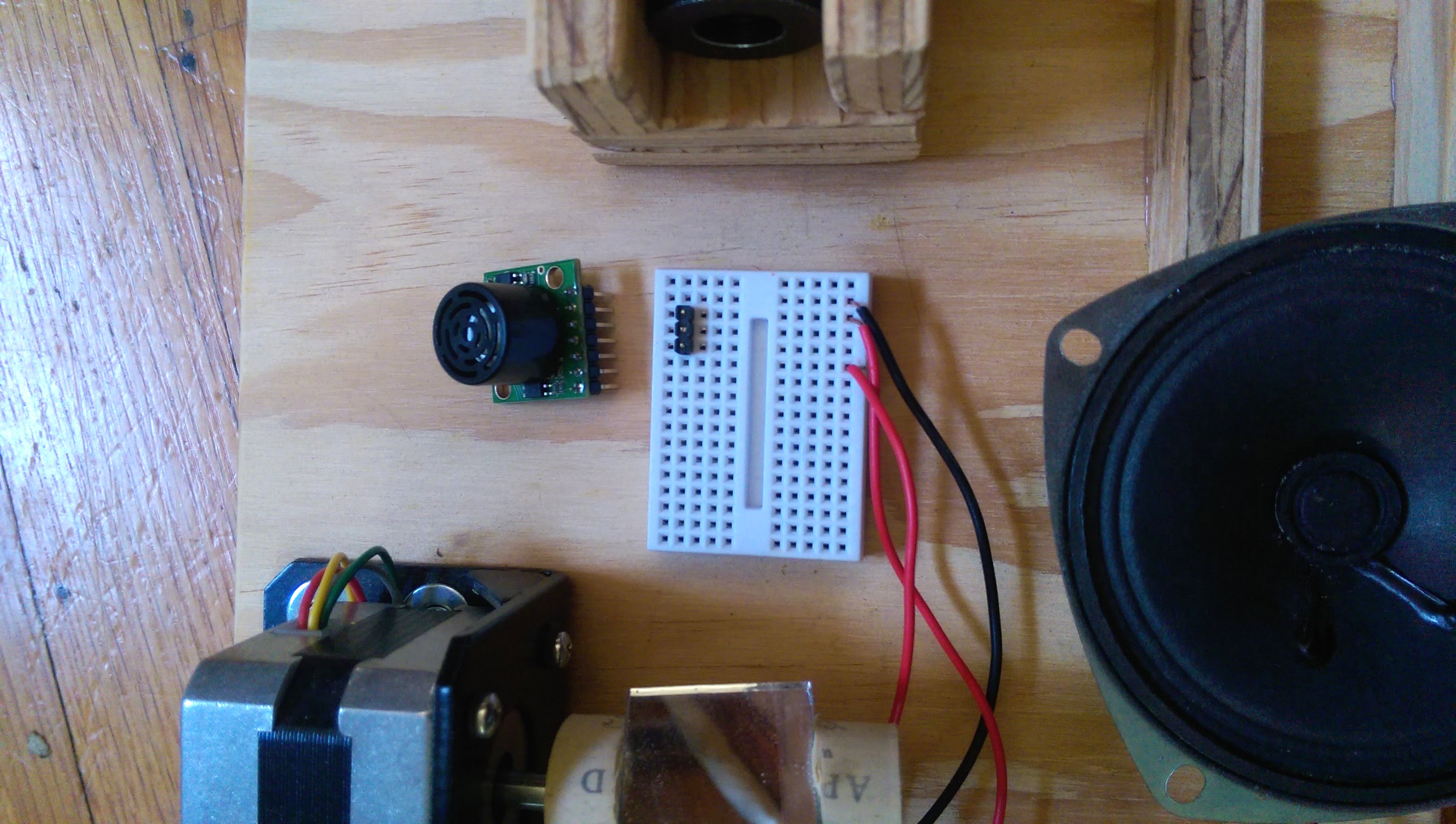
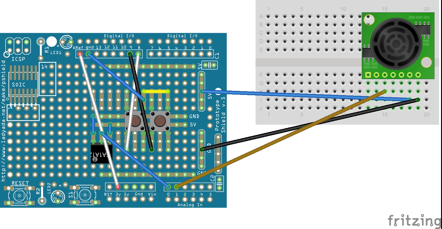
To achieve this effect, I added sonar using an ultrasonic rangefinder that can sense the distance of my hands from the sensor. I also gave my design the ability to play chords (polyphony) if you break two beams at once.

Laser Harp

The code is written from scratch in Visual Studio (which is free now). You can see all of my code on my GitHub page.

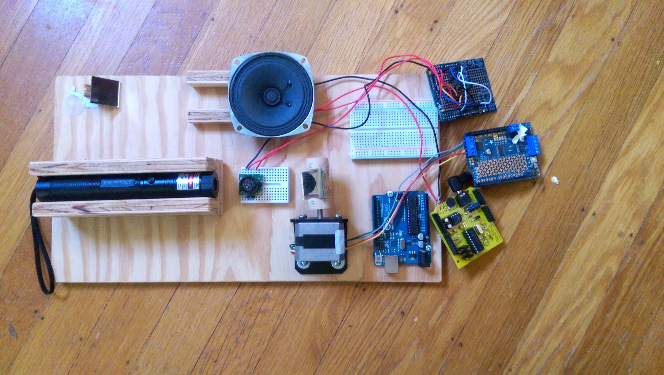
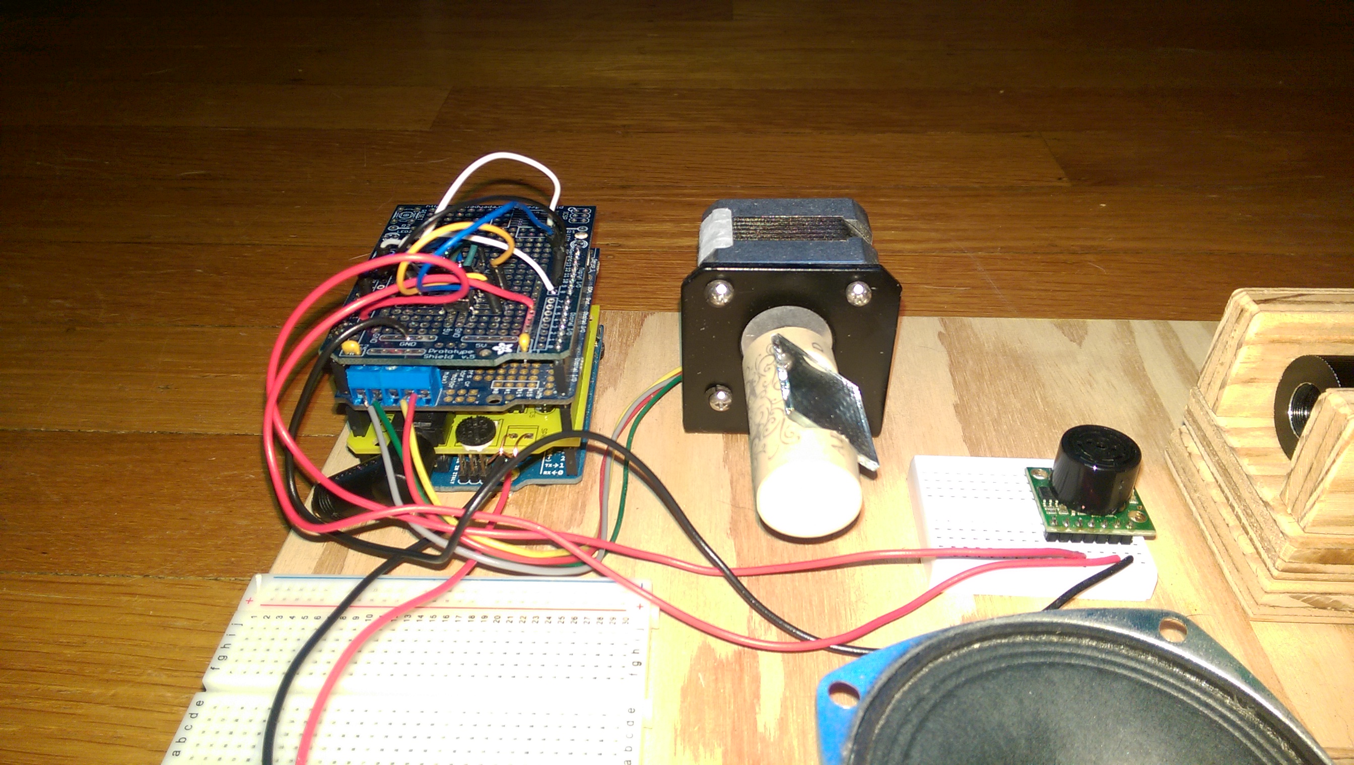
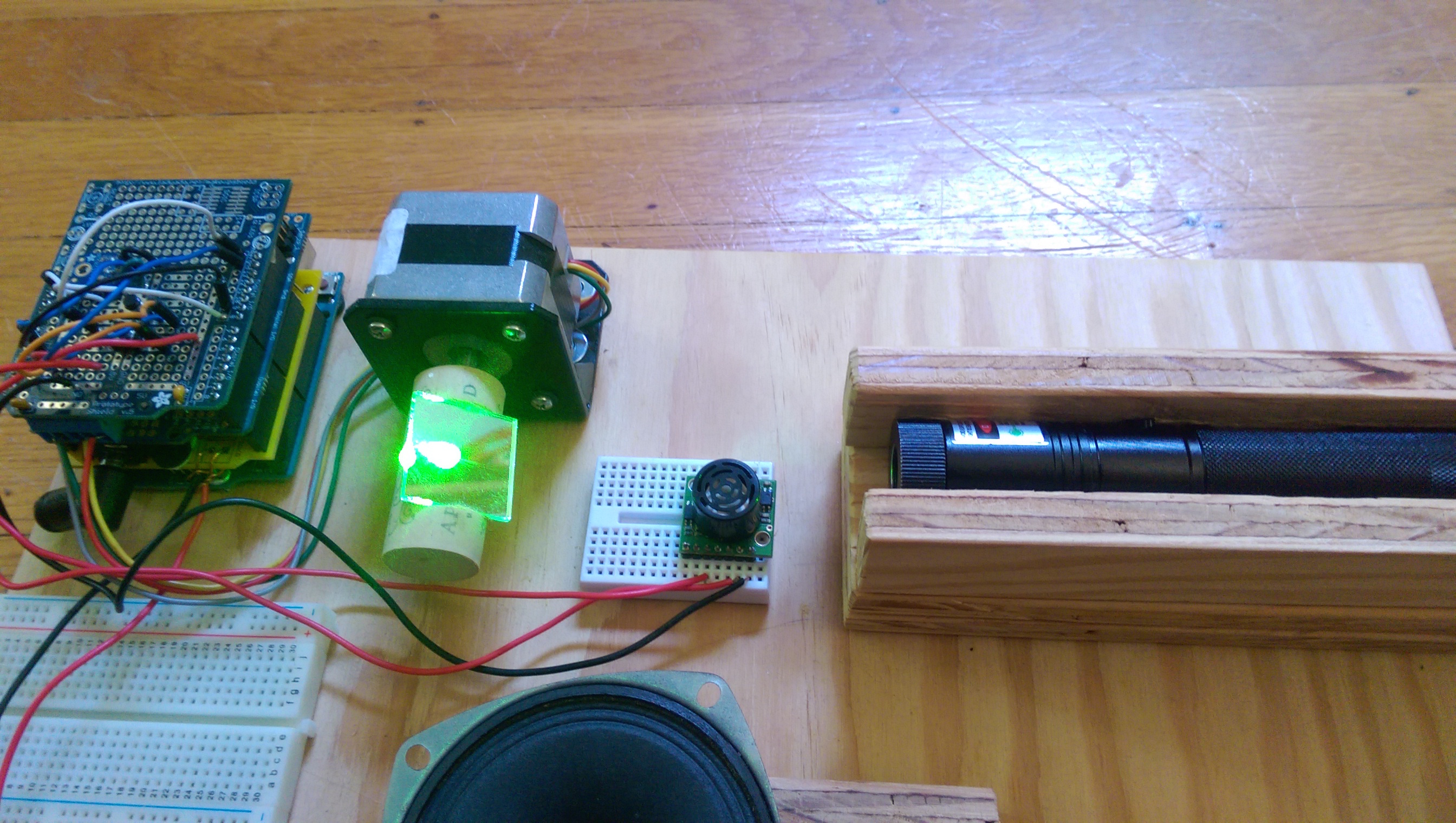
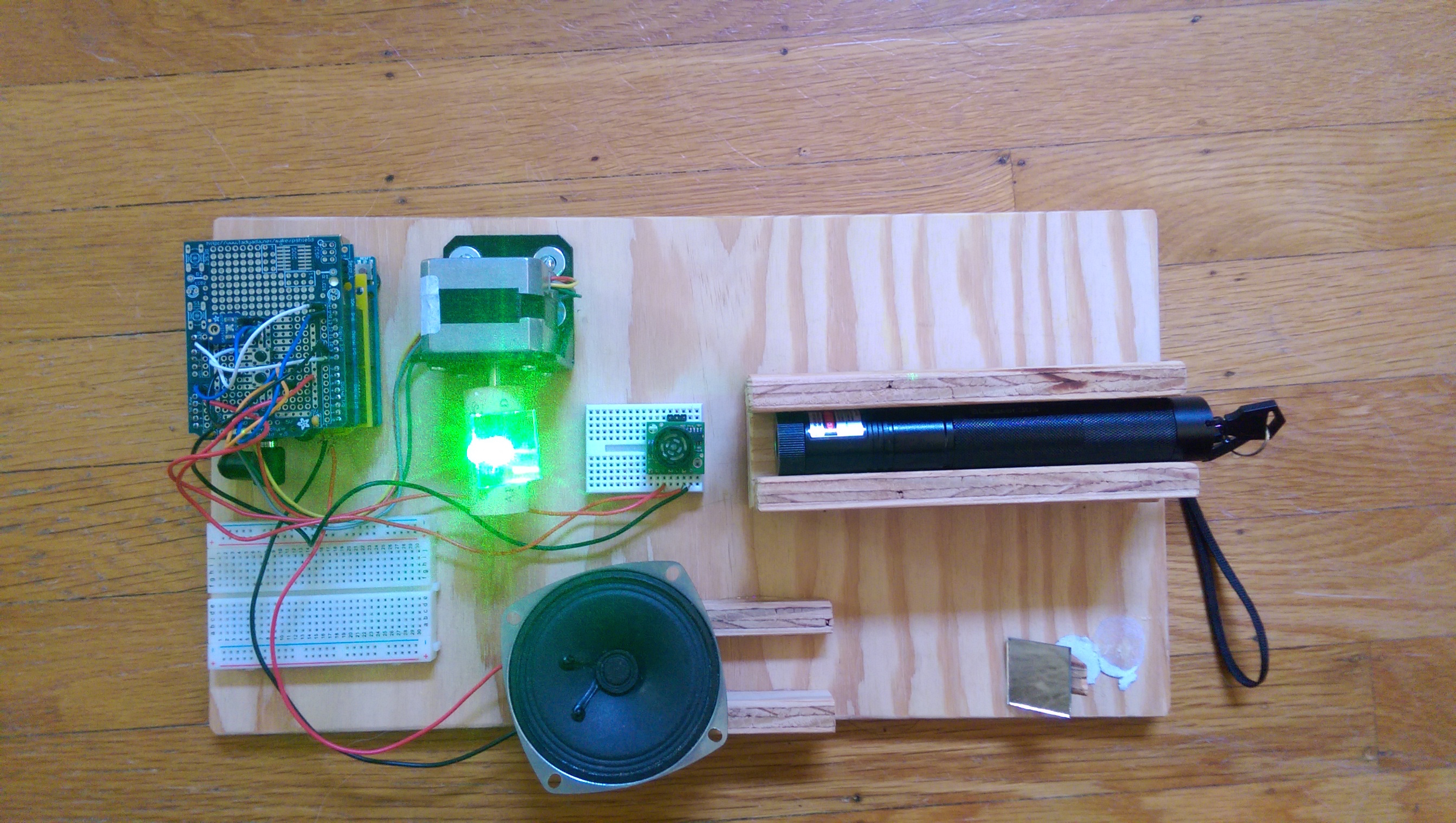
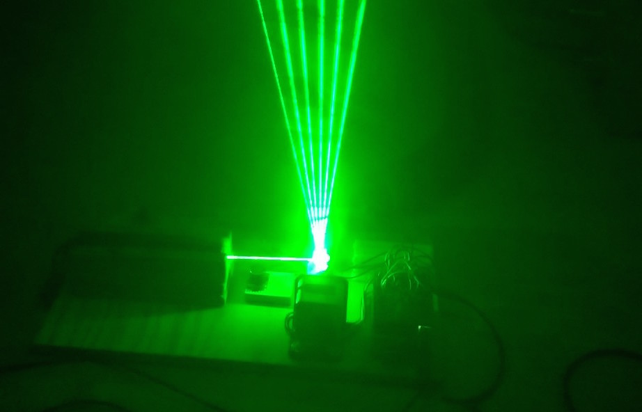
What I’ve built is known as a frameless laser harp. It fires a spread of lasers into the air. When you stick your hand into a beam, it plays a note.

Laser Harp Wiring Diagram
Wiring diagram for Protoshield or breadboard.

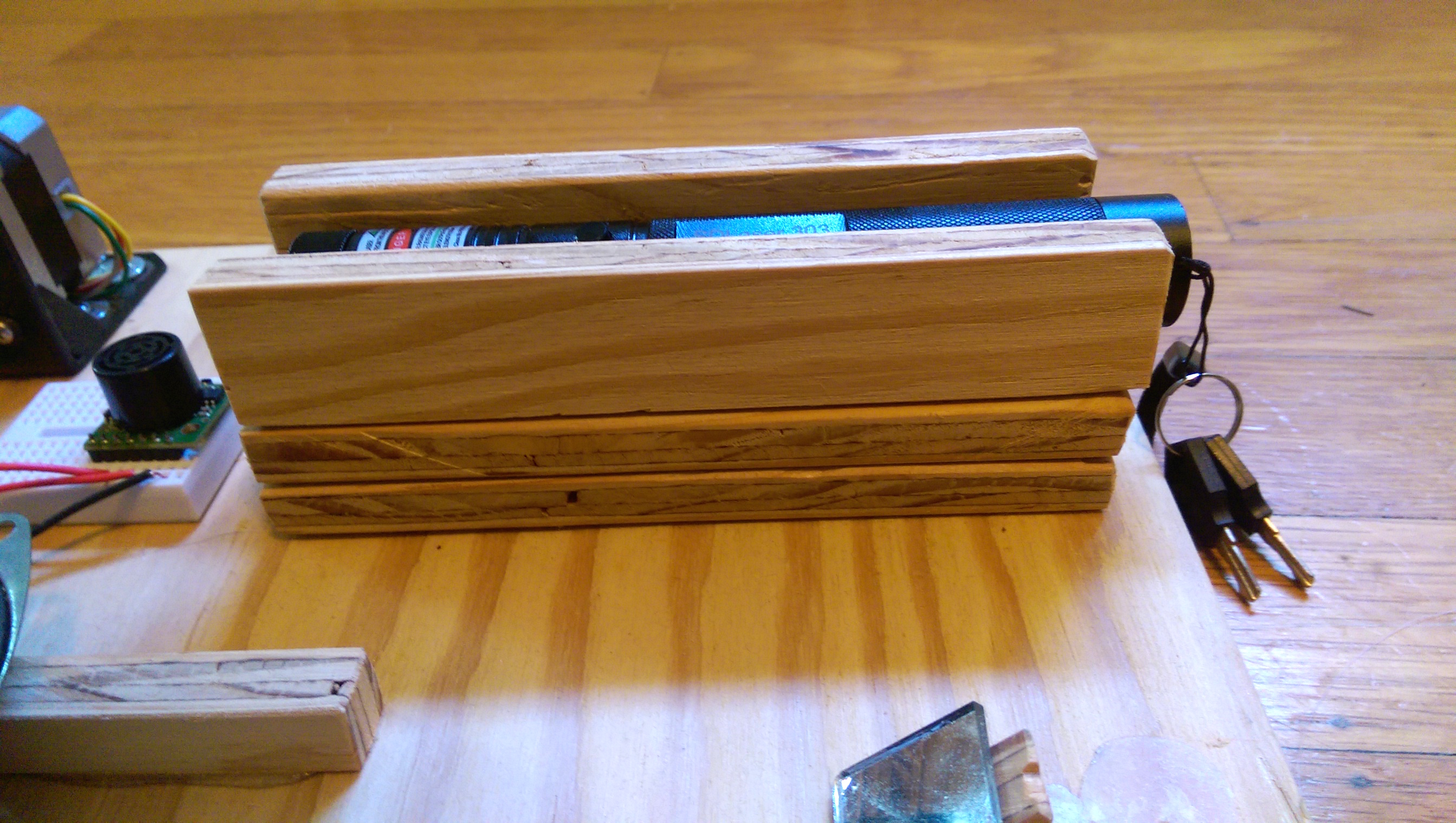
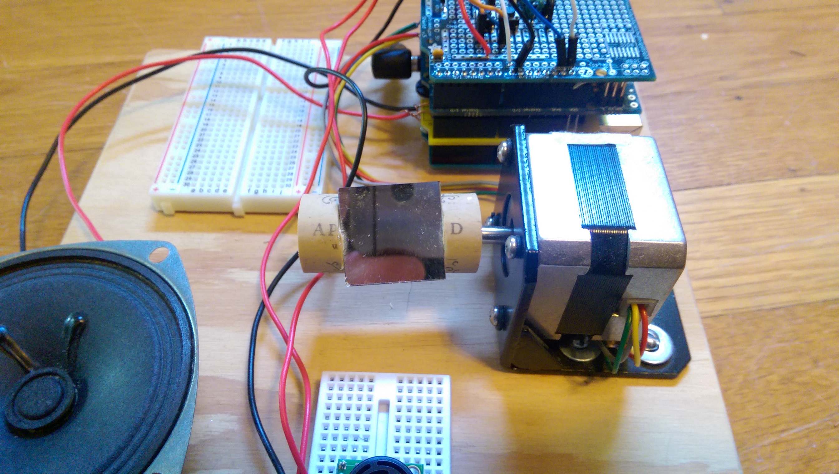
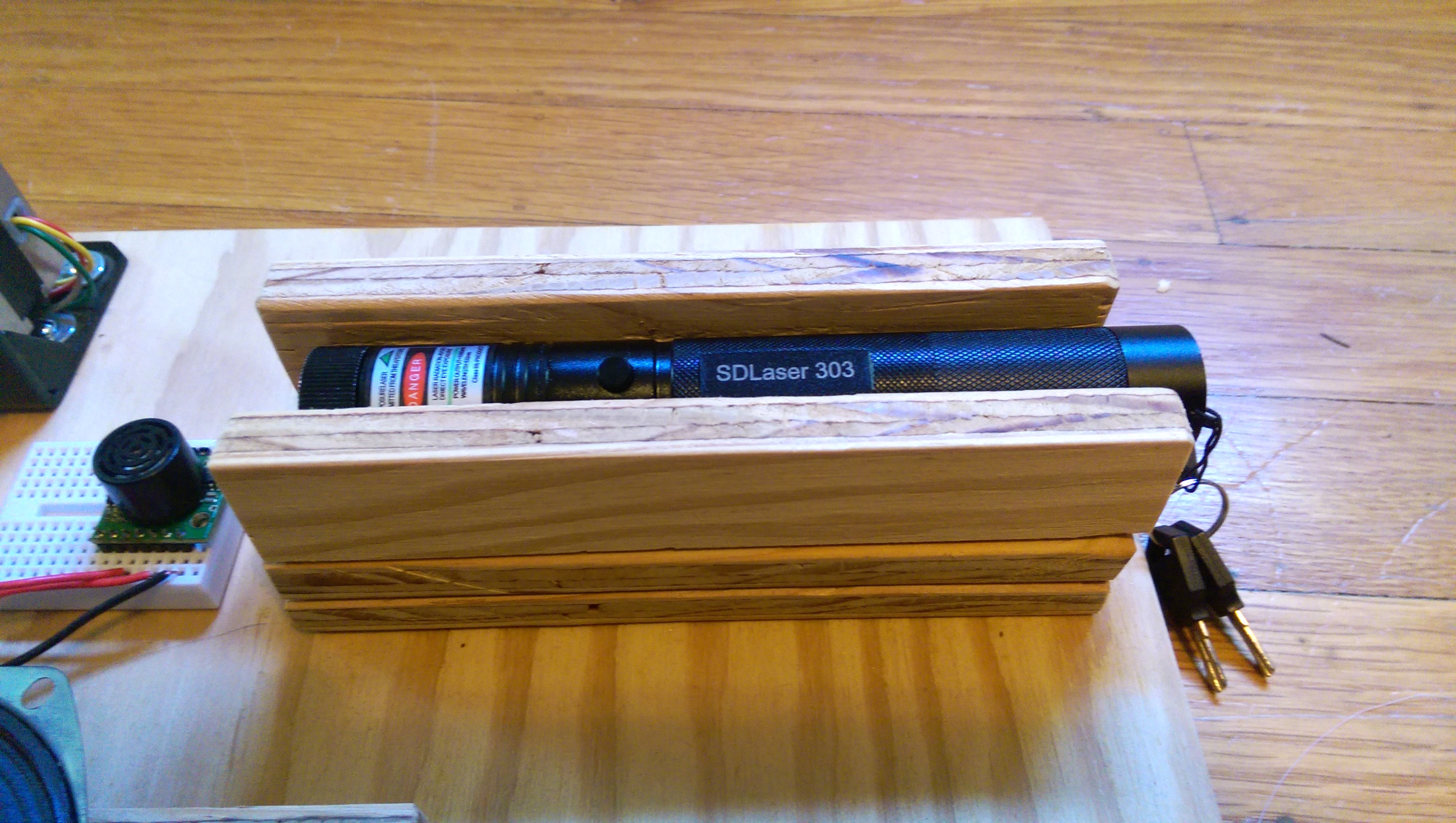
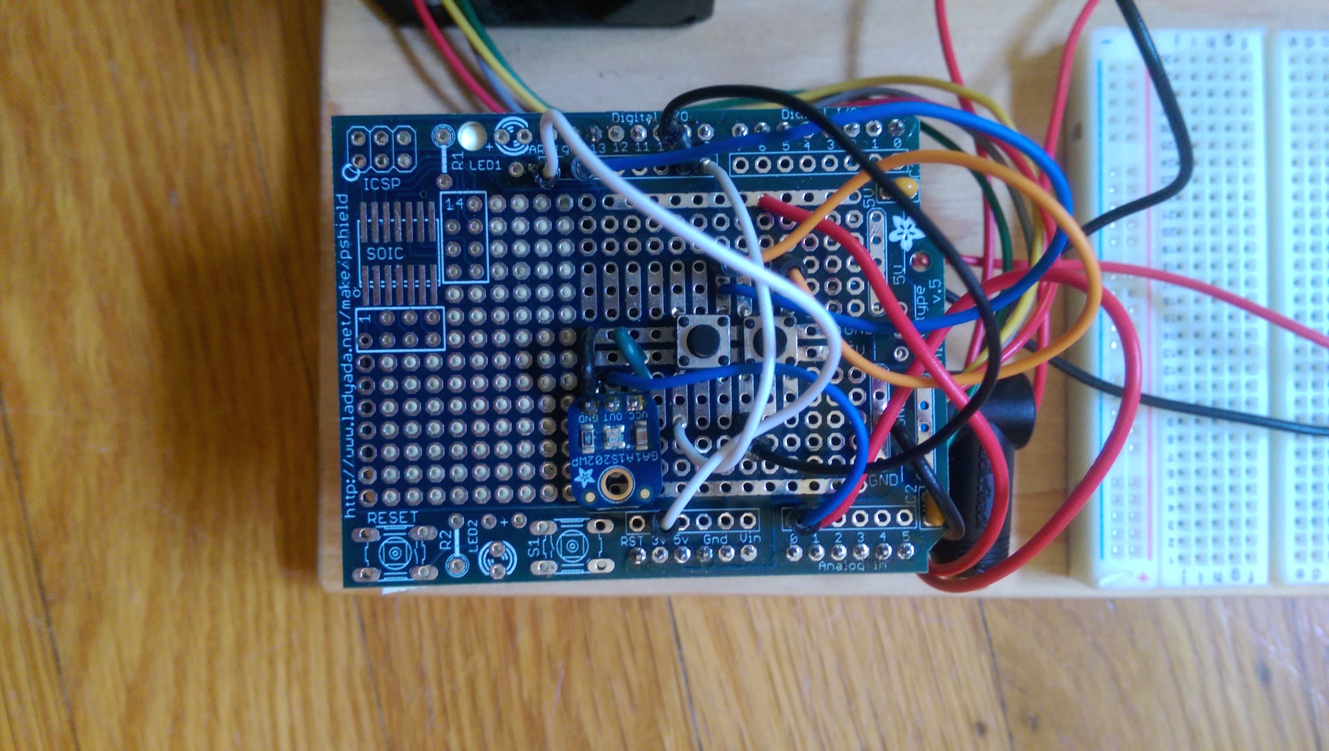
I’m using a single laser pointer for the laser beam. It fires the beam into a mirror attached to a stepper motor. That vibrating mirror turns the single beam into a fan of beams. When you stick your hand into one, a light detector picks up the reflected light, and that causes the Arduino to play a note.

YouTube player

Project Steps

Build the circuit boards

Assemble the Arduino, motor shield, Ginsing, and prototyping board using the respective instructions for each board.

I used a piece of tape to cover the LED on the motor shield board (center) because it was throwing off the light sensor. Also, you can use this photo as a reference for wiring up the motor shield to the stepper motor (notice the colored wiring).

The Ginsing board (right, yellow) offers two ways to get audio out from it. One is a wired speaker output (marked SPKR) and the other is a minijack audio output that can be routed to an external powered speaker or headphones. Both are connected in this photo but I found the best results using the minijack with an external powered speaker.

Also notice that I removed an LED from the Ginsing board (LED 1, lower left). I did this because it was throwing off the light sensor on the proto shield.

Build the base

All wood is ½” plywood. Cut a rectangle that is 8″×14″.

For the laser pointer mount, cut two rectangles that are 2″×6″, and two more that are 1″×6″.

We are going to make a U shaped channel to hold the laser pointer. It’s tight enough to JUST hold the laser pointer. So, if you roll it, the sides will press the button down.

Put one 1″×6″ piece on its side on a 2″×6″ piece, forming the side of a 6″ long channel. Put two or three screws on the bottom going up to hold it in place.

Lay the laser pointer in that corner and press the other piece in place. Not too tight, you have to get the pointer in and out, but tight enough to press the button if you turn the pointer so the button is on the side.

Do not screw the mount into the base until you’ve aligned the laser in step 5.

Stack the shields

Screw the Arduino Uno to the corner of the base, with about a ½” border. Stack the GinSing shield on top of it, then the motor shield, then the Prototyping shield.

Mount the motor and mirror

Screw the motor mount to the base, placing it about an inch in from the edge and an inch away from the shield stack. Attach the motor to the mount, so that the axle goes towards the inside of the base.

Take one mirror piece and hold it to the cork.

Use a knife to cut out a flat spot to glue the mirror piece; then, glue the mirror piece to that flat section.

Drill a starter hole in the cork; then press it onto the motor axle. Turn it so that the mirror is at a 45° angle and facing the large section of the base.

Set up laser

Now, take the laser pointer mount and stack it all together. Lay it on the base with the laser pointer in it.

Turn the pointer on so that it hits the mirror — and BE CAREFUL.

NOTE: It feels natural to lean over the board when you do this, but you’re turning on a laser and firing it into a mirror which will make it shoot up. Wear your eye protection, and watch where your head is located!

Once the laser is lined up straight with the mirror and firing straight up, add some screws from the bottom of the base to make sure the mount never moves.

Add mini breadboard

Finally, add the mini breadboard between the motor and the laser pointer, and if you want to test anything with the breadboard, put it next to the shields.

From this point on I’ll assume you’re using the prototyping shield, but the breadboard was handy when I was first making this and would be handy if you wanted to make changes.

Wire it up

Wire everything up using the wiring diagram. The ultrasonic rangefinder unit goes on the mini breadboard between the motor and the laser pointer.

The ultrasonic rangefinder unit goes on the mini breadboard. It only plugs in on one side, so to keep it straight, break off a few stackable headers and press them into the breadboard on the other side. That keeps the ultrasonic rangefinder pointing straight up.

Keep the wires clear of the light detector as much as possible!

Then get the code from Github and load it onto the Arduino.

Turn it on

NOTE: Watch your head! You are about to fire a laser beam into a moving mirror. Want to keep your vision? Be careful and don’t let your head EVER go over the laser harp!

If it doesn’t work, check over the wiring. The code also has a Debug variable — turn it to “true” and you’ll get output to a console, but it DRASTICALLY slows down the code, so the fan of laser beams doesn’t look as good. But it is great when things don’t work.

The light strings will be pointing… somewhere. Probably not straight up. Press one of the two buttons; you’ll see the laser strings slowly moving in one direction or another. That lets you adjust the light strings until they are pointing straight up.

If your ceiling is very uneven that can trip up the harp. If one string is reflecting too much light it can trip the light sensor. So check that, make the room a little dim, shoot the fog machine at it, and play the laser harp!

Conclusion

I’m pretty pleased with how this project turned out, though there are improvements that could be made, especially in the software. It’s still a little fiddly when it goes into other environments, so if I was going to redo this I’d add a button or two allowing me to adjust the amount of reflected light needed to play a note. That would let me adjust more easily for different environments.