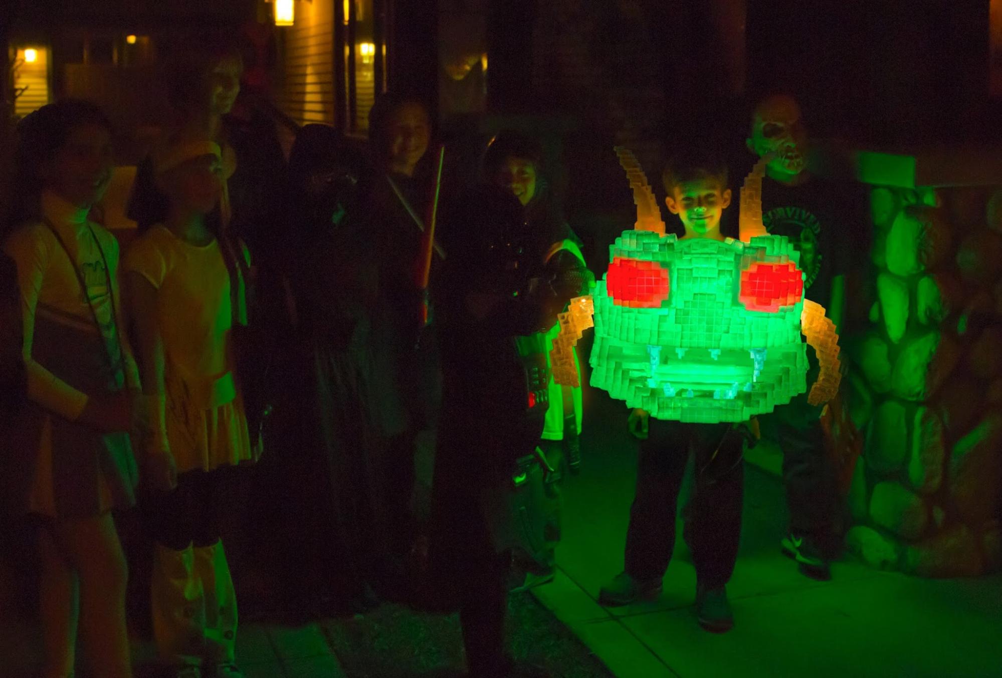
Last year after Halloween, our family came up with the crazy idea of making an 8-bit looking Centipede Halloween costume inspired by the movie Pixels and the classic arcade game. The costume would be wearable, illuminated from within by RGB LEDs, and even change colors like in the movie and video game.

Over the years I’ve made a few small molds and casts but nothing anywhere near the size and complexity this project would involve. By day, I work as a computer animation artist on films such as The Matrix, Blade II, Kung Fu Panda, etc. so much of this process would be a learning experience. This article is not so much a step-by-step how-to, but more of a story of how I built this large translucent costume! If you’ve tried to custom make something hollow and translucent at home, you know that it’s not an easy task! So let’s get started!

Project Steps

3D Designing

I started by designing and building a 3D model of the Centipede costume in Maya. I worked in real world units to work out the dimensions and details based on my youngest son’s proportions. I first modeled the shape of the Centipede and then used a plugin in Blender to “pixelate” the model into the 8-bit blocky cubes. I used the Remesh->Block plugin to convert the mesh to a block form. It took some experimenting to get the right resolution of “pixels” so that the major details were not lost.

3D design for Centipede costume
Pixelated model design (orthographic view)

Next I needed to figure out the best way to get the design out of the computer. I realized that even though this was going to be a costume for my 10 year old son, it was not necessarily going to be small! 3D printing a hollow thin shell at a size of 20 in. x 23 in. x 21 in. was out of the question due to size and cost. However, when I studied the model more closely, I did see a limited number of layers or slices similar to the way a 3d printer would build up slices. These thick “slices” could be built manually.

Sliced model design

Slicing the model broke it up into twenty-eight layers about ¾ inches thick. This thickness matched close enough to those insulation foam sheets sold at hardware stores. I also considered MDF and other ¾ inch wood boards, but due to their weight and how difficult it would be to cut this complex pattern, I decided to go with foam. The type of foam I used was white EPS insulation sheets, which are fragile with a rougher surface quality. I’d need to work on it later to fill it in. Looking back, another option could have been to use the closed cell pink/blue insulation foam (Extruded Polystyrene) instead of the EPS foam.

My next hurdle was how to cut out the intricate sliced patterns.

Centipede slices traced onto foam insulation

Building a Foam Prototype

After doing some research online, I decided to build a hotwire cutter to get clean cut edges and make fast work of cutting the foam. I had a lot of foam patterns to cut! There are plenty of guides online for building these so I won’t go into detail about the hotwire cutter build here. I ended up cutting the foam freehand without any straight edge guides due to the stepped nature of the slices. The slight imperfections gave more dimensionality to the pixelated look.

Hot wire cutter used to cut out foam slices
Hotwire cutter and Foam slices – cutting in progress

Once all the slices were cut out, I started sanding and sanding and sanding! Having 55 foam slices to sand really added up time-wise, especially with so many edges. The sanding wasn’t going to be perfectly smooth, but I smoothed out as much of the imperfections along the cut edges as possible. This step was a bit tricky because the foam is very fragile and it was a tough balance of sanding out imperfections vs. adding new ones.

Once all the slices were cut and sanded, it was time to glue and assemble the 3D puzzle laid out before me. I then used a combination of the hotwire cutter and a hot blade to carve in the grooves that run between each of the blocks. This gave a more detailed impression of the pixels and blocks.

Foam prototype assembled with carved pixel lines

Sealing the Foam

Now began the slow process of sealing and preparing the prototype for molding. Since EPS foam is very porous and cannot be spray painted or molded directly, I did a lot of research at this point to find the best way to seal the foam and hopefully smooth out some of the porous styrofoam look. As I found out, there are a many, many ways and opinions on how to do this. Anywhere from white Elmer’s glue and water to higher end commercial products.

I did a lot of tests using different recipes of glue, water, spackling paste, and water based paints. In the end, I found a water based latex paint that sealed and smoothed out the styrofoam pretty well after applying 2-3 layers of it (as opposed to the 5+ glue layers). One side note: I decided against some of the commercial products because most were too thick and would have smoothed out too much of the small pixel grooves.

One extra bit I added was some spackling compound to the more prominent areas, like the front and top. This helped smooth those areas out more and gave better definition to the pixel grooves.

Finished and sealed foam Centipede prototype

Making a Mold

Once the foam prototype was sealed, it was time to start making the mold! A little backstory on the decision to make a mold versus other processes like vacuum forming: I initially planned on trying to vacuum form the prototype by splitting it up into the six main sides, but after several tests I knew that the 90 degree draft angles were going to be extremely difficult to release from the bucks. Also, due to the complexity of the prototype, with pixelated 90 degree angles and large undercuts, I decided that a rubber jacket mold and mother mold was the best way to go. The rubber jacket mold would be able to stretch and pull away from the corners more easily.

Rubber Brush On Mold

I started by planning out how many sections to divide the mold, considering undercuts and angles of the prototype. I decided to do a two part rubber jacket mold and built a clay base using plastalina clay by rolling the clay with a rolling pin.

Plastalina clay base around prototype

Then I started the brush on mold process by using a release spray to help remove the rubber more easily. I used Smooth-On Brush-On 40 and tinted each layer a different color so it was easier to find thin areas – the first layer of rubber coat is important when capturing all the details.

Brushing on first pass of rubber jacket mold

After the first coat, start to build up thickness to fill in as many undercuts and sharp corners as possible. The more the rubber fills in and smooths out the angles, the less parts you’ll need to make for the outer hard shell mold.

Rubber jacket mold ready for rigid outer mold

Making a Mothermold

Once the rubber jacket mold was fully cured, it was time to plan the rigid outer mothermold. Since the rubber mold still had large undercuts, I needed to break up the mothermold into sections to ensure the mold did not lock. The mouth was particularly challenging because of the large depth and right angles. Instead of filling the mouth with expensive rubber, I filled in the shape using an expanding foam. This foam provided enough support for the mothermold while being flexible enough so it could be removed when demolding. Finally, dividing lines were drawn and clay walls built with keys to help with alignment.

Clay dividing walls built up ready for mothermold

I used Ultracal 30 with stranded fiberglass to make the outer rigid mold. The Ultracal 30 was very strong, but it added quite a bit of weight to the mold. It helped keep costs down quite a lot though. This was another area where I learned that the extra costs might have been worth it in the long run. A lighter but more expensive option, like fiberglass or Smooth-On Plasti-Paste, would have kept the weight down and made it possible to rotocast (more on that later).

Ultracal 30 mothermold sections

Because I needed to add LEDs, electronics, and a support cage inside the Centipede head, I decided to cast the two halves separately and extend each half beyond the centerline so that there would be about one inch overlap. It made the assembly much easier.

Rubber jack mold and rigid mothermold separated from prototype (front half)

Now after all that work, only half was ready for casting and it was time to repeat the process for the other half!

Ready to mold the second back half of Centipede head

At the same time, I started making the prototypes and molds for the arms and horns with EPS foam. Since there are no small groove details, the arms and horns are coated with the thicker Smooth-On Epsilon. This reduced the number of coats to 1 or 2 and gave a smoother finish to the foam.

Creating clay walls with pour spouts
Two part mold for horn ready for casting

Casting a Hollow Translucent Centipede

Casting was tricky due to the size, weight, and thin translucent shell requirement. I needed enough thickness to be rigid enough to hold the shape, yet light enough for my son to carry. For casting, I used Smooth-Cast 326 resin, because it gave about a 5-10 minute working time. As expected, due to the size and weight of the Ultracal, I was not able to rotocast each half. This is where fiberglass or Plasti-Paste might have been light enough to allow for rotocasting… maybe. Instead, I brushed on three to four layers over many nights. The advantage here was I was able to clearly see and judge the actual thickness. One big side note is to make sure to coat the rubber mold with enough of the right release agent! I had spots where there wasn’t enough and it made it very difficult to remove the thin fragile cast.

Brushing on Smooth-Cast 326

Once both halves were cast I built an aluminum support frame inside that held the two halves together using bolts. Also, on the frame I attached shoulder straps.

First test fitting!! Happy it fits!!

Electronics and LEDs

Installing the electronics and LEDs was much more straightforward compared to some of the other steps of this project. I had worked with RGB pixels before when I created a 1800 pixel matrix board and some other LED projects for a Holiday display. For Centipede, I purchased a 5V RGB LED strip that has individually addressable LEDs (WS2812b – 30 pixels/meter) and an Arduino UNO to control them. The design called for the LEDs to wrap around an inner cylinder shape just larger than my son’s chest and then split off into the eyes, arms, and horns. I needed the LEDs to be programmable so that I could animate the colors changing from a red/green combo to purple/yellow color when a button is pushed. The inner aluminum support frame was wrapped with Coroplast (looks like plastic cardboard) and then the LED strip was wrapped and zip tied to this.

I cut the LED strip in sections and soldered together wire to extend the LEDs between the arms, eyes, and horns. I was then able to program those LEDs in different sections to the appropriate color – eyes are red, body green, horns and arms are orange.

RGB LED strip
Inner frame and Coroplast shell for LEDs to attach

Battery Power

Since the Halloween costume needed to be mobile, there was a bit more consideration for what type of battery would power this many LEDs and the Arduino. Powering a few LEDs with a battery is pretty straight forward, but the Centipede had 125 RGB pixels which translates to 375 LEDs! LEDs are very efficient but this many can draw a lot of current. One single white pixel at full power draws 60mA. Luckily, I didn’t need the pixels to display white, but if I had, all 125 pixels set to white at full power would pull a crazy 7.5 amps! This is way beyond the max current output for most batteries. Luckily for this project, the max I would ever have displaying per pixel would be two LEDs to make a purple/yellow color.

The battery also needed to be as lightweight as possible and needed to last for at least two hours of Trick-Or-Treating. Alkaline batteries would not be able to handle this amount of current nor the amp hours (how long the battery lasts). After a lot of research on various battery types – Li-ion, Lipo, LiFePO4 – I discovered it was challenging to find a good battery that had enough max current, amp hours, and safety protection.

One battery type I considered was RC Lipo battery packs because they are high current and have decent amp hours, but unfortunately they are not safe for wearables. These RC Lipos usually don’t have Battery Protection Modules (BPM) that protect the battery from overcharging, or worse, over current draw. There are some RC Lipo’s available with BPM, but in the end I found phone USB chargers already have those circuits built in, have a nice form factor, provide 5V, are lightweight, and also can have very high amp hour ratings. The one drawback is that the max current on these batteries available at one time is 2.4A Max per port. That could work if I could get the amps down around 2A.

To reduce the current, I did some tests. I was able to cut the power down by half while making it seem like there was only a slight drop. The LEDs were still very bright and I was down near the target of 2.4A max. To get the rest of the way, I lowered the brightness more when switching to the yellow/purple color combo, which has the highest current draw.

Here are the calculations for the required battery:

125 pixels x 40 mA / 1000 * .5 power = 2.5 Amps (40mA is for yellow/purple colors which need two LEDs on at a time )
40 mA x 2 hour * .5 power = 40 mAh x 125 pixels = 5,000 mAh (5Ah) battery size

Total: 2.5 Amp Max Current and 5 Amp Hour Battery

The battery that best fit my needs was the Anker PowerCore 20100, which provides a huge amount of amp hours of 20000 mAh, 5v output, 2 ports providing 2.4 A each, relatively light weight, and, most importantly, MultiProtect Safety!

The battery ended up working better than expected and lasted over 3 hours on Halloween night and 6+ hours in the days after that. Even with the power reduced to 50% it was still bright enough to illuminate the area for all our fellow Trick-Or-Treaters. He definitely was easy to spot!

Illuminating the way for other trick-or-treaters

Trick-Or-Treating

The project took the help of the entire family! My wife and two boys worked hard sanding styrofoam, painting, molding, and casting for many late nights and weekends. Even though we started months before, on Halloween day we still were not anywhere near complete! We weren’t sure we were going to finish since we hadn’t started the inner framework, and the arms and horns hadn’t even been demolded yet to look for issues. We didn’t start the LEDs until 2pm on Halloween and they needed to be cut, soldered, and installed.

We worked up until the last second and luckily everything came together. The planning paid off! It was a lot of work for all of us, but seeing the look on both of my sons’ and wife’s faces when the costume came together was worth it! On Halloween night, my son had such a great response and reaction from friends and fellow Trick-Or-Treaters! As we walked in a busy Trick-Or-Treating neighborhood, Centipede lit up the dark night, turning everyone’s head and causing many looks of amazement. The most asked question… “How did you MAKE that!?”