VERN ADERMANN is CEO/founder of CityWide Co. and an engineer with 20-plus years’ experience in robotics and process systems in the semiconductor and aerospace industries.
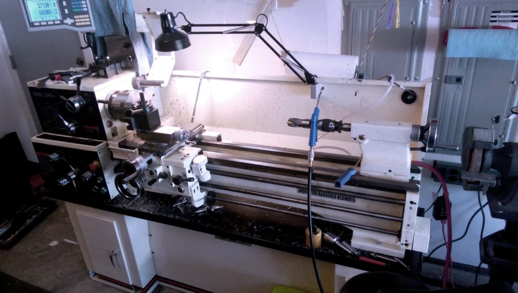
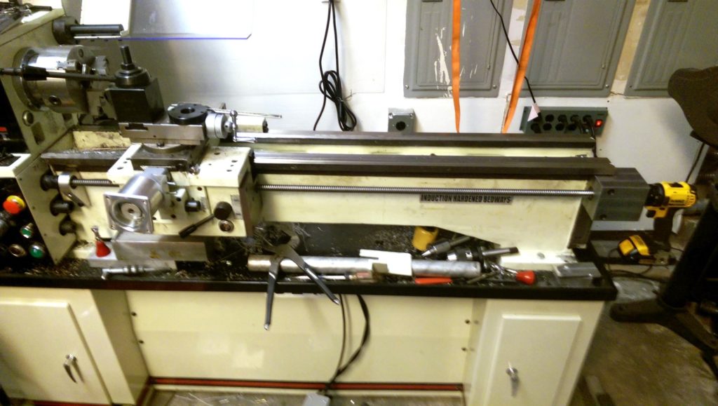
Our home shop includes a Jet GBH-1340A metalworking lathe with a Digital Read Out (DRO), and we’d been discussing adding CNC control, because certain types of parts are extremely difficult to make with high precision without a computer in the driver’s seat.
This project is from the pages of Make: Magazine. Subscribe today!
But we approached the project with a certain amount of procrastination. We initially selected a Variable Frequency Drive (VFD) controller for the spindle, NEMA 34 stepper motors, and drivers for the lathe axes based on what we found inside our Tormach 770 mill. We also found a parallel CNC control card online. One of our primary considerations for the parts we selected was “cheap,” although in the end that would cost us.
The parts arrived and we set them aside for about a year while other projects took priority, only infrequently revisiting this project to take measurements or ponder how exactly to mount the steppers. It was the abrupt failure of the Jet’s spindle motor that brought this project back into focus. We pulled out the parts and started the conversion in earnest.
COST:
$2,500–$2,800
There are three main parts to a CNC conversion. They are: (1) modification of the machine itself, (2) construction of a control box, and (3) setup and configuration of a control PC.
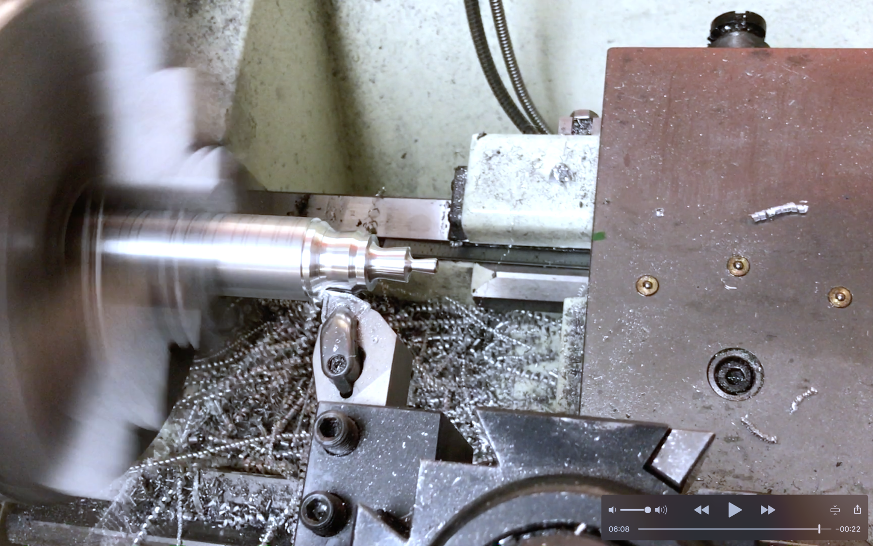
Our lathe has a 13″ swing and a 40″ long axis. Spindle speed is normally controlled via a gearbox behind the spindle, driven by a single-phase 230V motor. No modification to the gearing was required; we simply selected an optimal gear setting and under the CNC the speed would be controlled by the VFD controller. The failure of the original single-phase motor was actually a stroke of luck, because replacing it with a three-phase motor provided more control and allowed for a top speed nearly double the 1,750 RPM the original motor could manage. Best of all, the VFD was able to convert 220V from single- to three-phase. The original electrical control box was removed from the back of the lathe and some of the control relays and other parts cannibalized for use in the new control box.
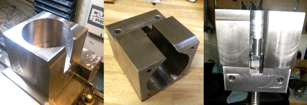
First Z-axis motor mount being milled.
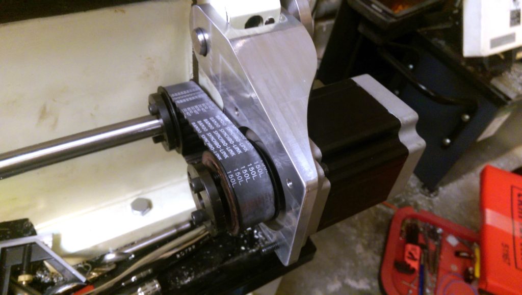
The carriage that holds the cutting tools had two options for controlling its Z-axis movement. (On a lathe, the Z-axis is left-right while the X-axis controls the diameter.) There’s a primary leadscrew for general-purpose cutting, and a second leadscrew that rotates in lock-step with the spindle for cutting threads. Both of these are driven from the same gearbox, and engaged to move the carriage via control levers on the carriage itself. We opted to remove the thread-cutting leadscrew and the bar that controlled the primary leadscrew. This would allow us to drive the primary leadscrew via a stepper motor mounted at the opposite end, and attached by a belt and pulleys. The primary leadscrew took just over 50 rotations to move the carriage 1″ and we hoped this would provide some degree of precision control.
First attempt at Z-axis motor drive.
Using a CNC mill, we crafted a motor mount to bolt to the lathe on a swivel, much the way the alternator in a car is mounted to allow belt tensioning.
Replacing the cross slide: Original X-axis hand crank.
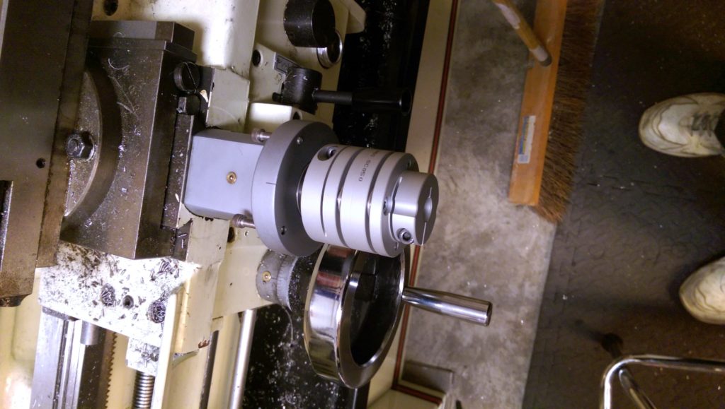
For the X-axis, aka the cross slide, the obvious choice was direct drive by the stepper. We removed the hand cranks from the machine and milled another aluminum mount. The leadscrew was attached to the stepper via a beam coupling to alleviate stress.
Cross slide motor assembled: the new X-axis stepper.
We made no modifications to the lathe tailstock. This will remain under manual control while the computer handles the heavy lifting for the X and Z axes.
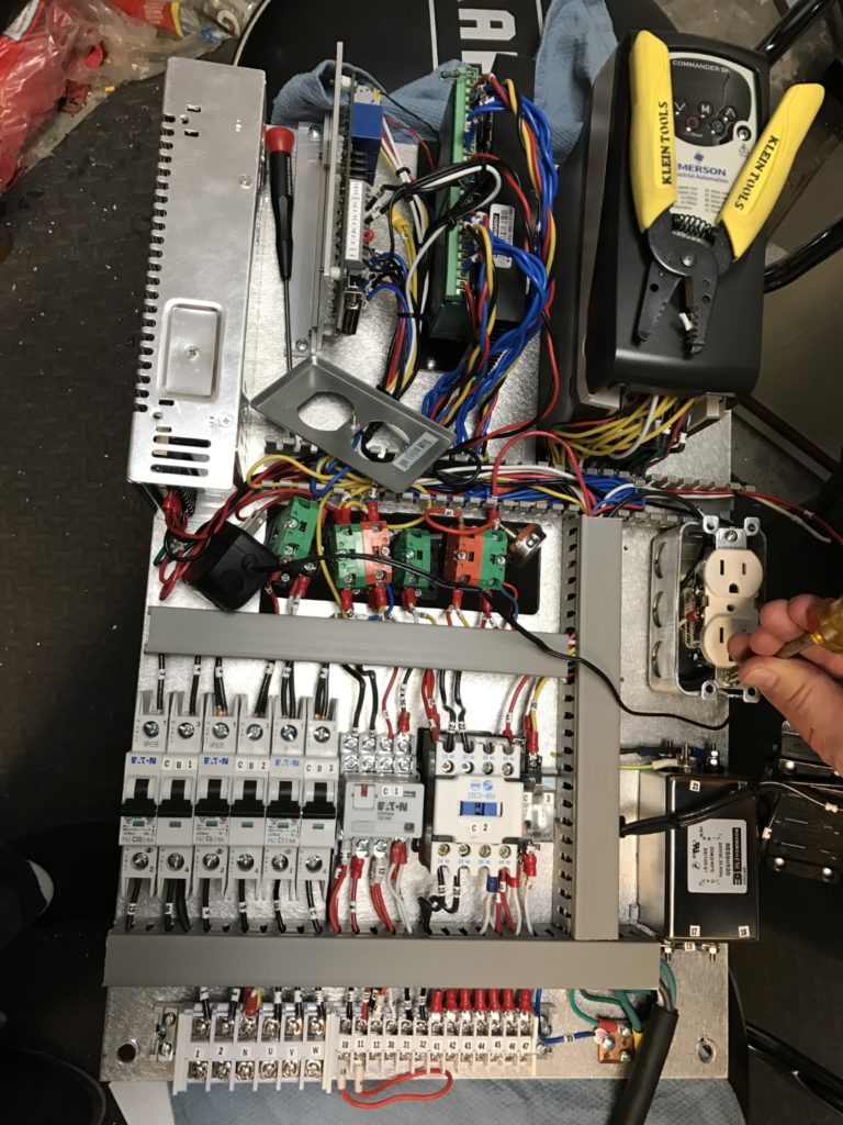
The original Jet control box was far too small to fit all the components required to control the lathe, so we found a 24″×16″×10″ box online that would fit everything. A 10″ depth was perhaps overkill, but gave ample room for mounting cooling fans and switches on the side of the box. And it was sturdy enough that when mounted on back of the lathe it could support a monitor and stand.
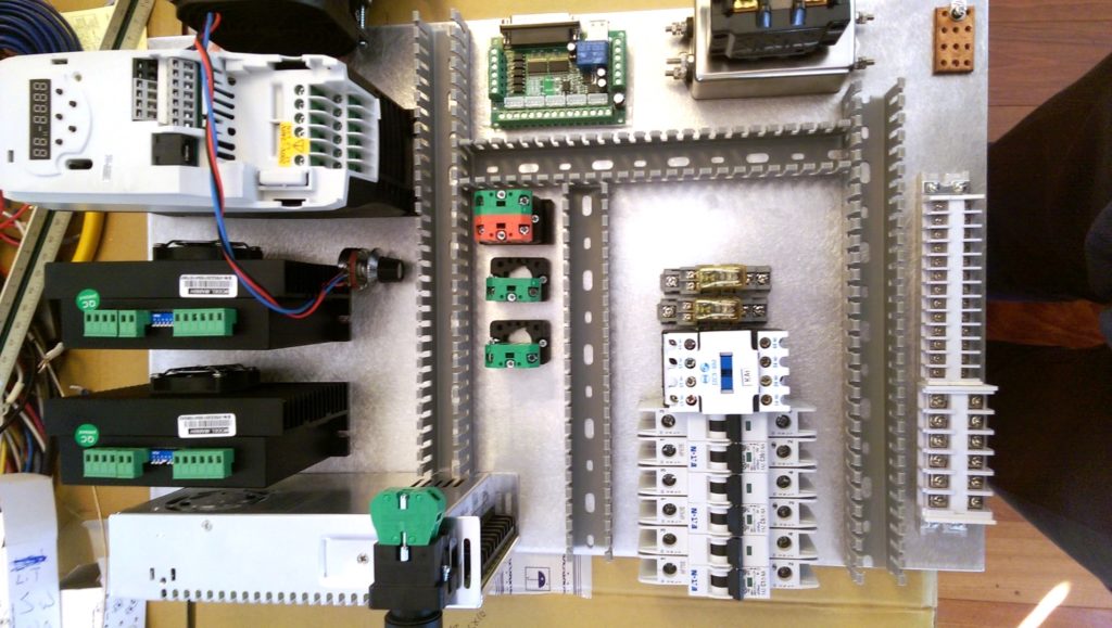
Laying out control parts.
We mounted the components on a 1/8″ sheet of aluminum which could be removed from the box for easy access, and which also would act as a heat sink. Holes were cut in the aluminum and the back of the box for a set of manual spindle controls.
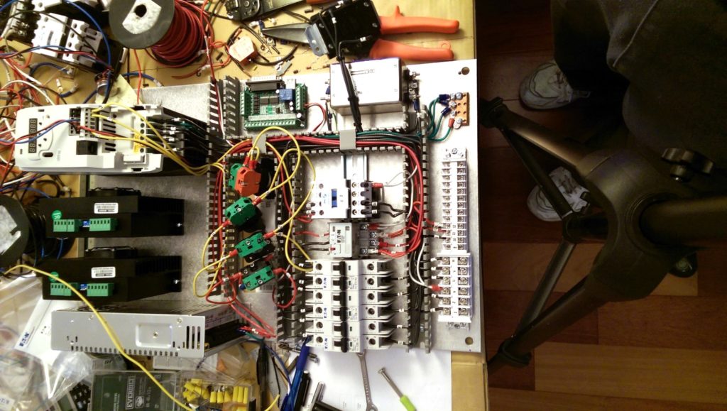
Wiring in progress.
Open slot wiring raceways were added to keep the wires from becoming a tangled mess.
Carefully labeled junction.
Throughout the process a schematic was maintained in Visio with all connections carefully numbered, and the wires were labeled at both ends to match.
Altogether, assembly of the control box took about 60 hours.
While many CNC projects use a parallel port to drive the machine, they often don’t use the latest and greatest PC hardware. First, many modern PCs don’t have parallel ports, but also many modern processors have optimizations which make them very good at running software but very bad at directly bit-banging I/O ports for time-sensitive hardware control. It’s not a problem for a PC driving a printer because USB has offloaded the hard work, but in our experience with a CNC mill, the wrong hardware/software configuration can result in a cut being made tens of thousandths off from what the G-code asked for.
Fortunately, the major options for CNC software have lists of computers that have been tested, so less guesswork is required. We opted for an old Dell Optiplex with a Pentium 4 processor running LinuxCNC. We were able to purchase two of these (so we had a spare) for $30 apiece at a local recycled PC store.
LinuxCNC offers a very capable set of control options and is well supported by a community of dedicated computer geeks. Following the instructions from the website, installing LinuxCNC was straightforward and it ran well on our ancient PC. Using their StepConf program we were able to configure individual pins of the parallel port any way we wanted. We discovered it would have been worthwhile to set up LinuxCNC before we had purchased any of our control hardware. They had default configurations for several different types of hardware, some of which we’d been unaware of when we made our original purchases.
It didn’t take long and our parallel control board was lighting up like a Christmas tree when we clicked buttons. No magic smoke came out. We should have been golden. Instead, nothing worked.
It’s perhaps not fair to say nothing worked. There were hints that some things were almost right. One of the stepper motors would make a single chug noise when we told it to turn. The LED on one of the stepper drivers would stay green up until that point, and then it would turn red. The other stepper driver defiantly went red as soon as power was applied and sat there glaring at us like the eye of Sauron.
We reviewed all our wiring. We compared our setup to how the Tormach was wired; no problem there. It was when we borrowed an oscilloscope to check the output of our CNC control board that we found the first problem: the output signal voltage was only rising to half the level required by the stepper drivers. Our $20 control board was garbage. We decided to loosen the wallet a bit and found a $99 board on another website. When it arrived, it was branded with a different website: CNC4PC.com. It was also six hardware revisions out of date from their newest offering. It did provide the right voltage levels, so we called it “lesson learned” and hoped the steppers might work better. They did not.
I mentioned earlier that much of what we put in our own control box was based on what we found in our mill. These stepper drivers were the same model MA860H as the mill had, so with visions of mill repair bills in our heads we started swapping our suspect parts into the mill. The stepper motors went first and to our great relief they both worked perfectly. The stepper drivers went next, and neither would function. The eye of Sauron continued to taunt us. Suspecting this might have been our fault we ordered a new pair of the same model. Both of these were dead on arrival as well. One would not function in the mill at all and the other would turn but only in one direction. Clearly these drivers were not a reliable solution.
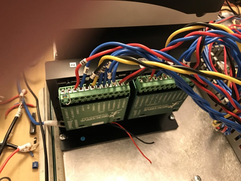
Frankenstein motor driver: New GeckoDrives mounted in carcass of failed motor driver.
More online research brought us at last to GeckoDrive, and we could not be happier. These boards worked well the first time we hooked them up, and both of the Gecko units together fit in the same space as one of the earlier, cheaper drivers. At the voltage required, the GeckoDrives would need a heat sink (not included). The cheaper drivers included a large heat sink and fan, and since the fan was the one part of that driver that worked reliably, we found much satisfaction in mounting the GeckoDrives in the hollowed-out carcass of the dead driver. This solved two problems at once.
Control parts assembled, not in housing yet.
The new parallel control board was much larger than the original and now we could mount it in the space left by one of the original stepper drivers.
One note about stepper drivers: They come in analog and digital flavors. On YouTube you’ll find videos comparing their behavior. These show, and we agree, that digital drivers provide much smoother and quieter stepper motor operation. They seem well worth the added price.
All the pieces were in place. We could control the steppers with UI buttons or G-code instructions, and with a rudimentary attachment of the motors to the leadscrews we could move the carriage along both axes.
We didn’t know the exact ratio of leadscrew rotations to lateral movement, so it took a bit of trial and error to find the right settings in the LinuxCNC StepConf program. StepConf asks you for several values: motor steps per revolution, driver microstepping, pulley teeth ratios, and leadscrew pitch. If you’re uncertain on these values, it’s worth noting they just get multiplied into a single value that means “steps per inch.” If you set all but one of these values to 1 (doesn’t matter which), you end up with the remaining value being a large number that you can tweak with great precision. The process we followed:
Move the carriage to an approximate known position, moving from left to right. In your CNC UI, reset your offsets so the position reads 0.
Measure the position of the carriage.
Using G-code, move the carriage 1″ farther to the right, i.e. Z1.
Measure the new position of the carriage and calculate the difference in inches.
Divide your “steps per inch” value by the distance moved, for a new steps per inch value. For example, if your steps per inch is 20000 and you move 1.015″, your new steps per inch would be 20,000/1.015 or 19704.
Repeat, until issuing a command to move 1″ reliably results in 1″ of movement.
It’s critical that your measurements always be made after moving the carriage in the same direction because your leadscrew will almost certainly have some backlash. If you measure after moving in opposite directions, your measurements will be off by up to the backlash amount.
The DRO was still attached to the lathe and this greatly simplified the process of comparing instructions on the PC to the actual carriage movement. Following our process, we should have arrived at a steps per inch value that would give consistent results no matter where on the axis we measured. It worked for the X-axis, but along the Z-axis measurements varied by as much as 0.012″ depending on where they were taken. Something was horribly wrong.
Leadscrews can be inaccurate, but the screw would have to be very bad to have the error increase and decrease again and again over 40″. The problem was that in addition to the headscrew, there were other gears and worm drives involved in Z-axis movement. We needed to account for inaccuracy across the entire train. The Z-axis backlash was similarly awful. LinuxCNC has ways to compensate for this, but it would have required finding the error at every point along the 40″ axis. It would have been nearly impossible to achieve the precision we wanted. The gear train would have to go.
Measuring where to mount a Z-axis motor mount.
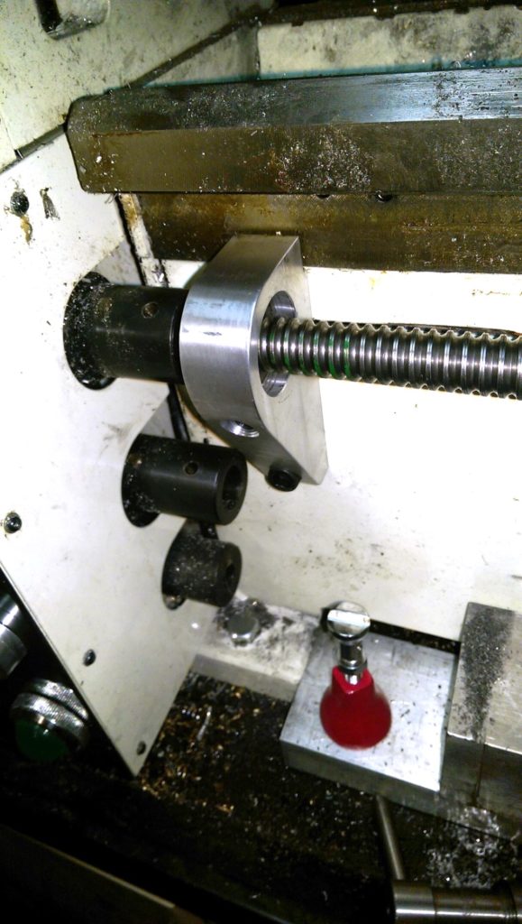
A precision ball screw can virtually eliminate backlash, for a price. One company quoted $3,500 for a 40″ ball screw. In the end, we purchased a ball screw and nut for $225 from Roton Products in Missouri. It required modification to fit the bearings we’d purchased, $336 at a local grind shop. The Roton ball screw had 0.007″ backlash, but at least it was consistent and easily compensated for in LinuxCNC.
Our second Z-axis motor mount: midway through milling, completed, and mounted with ball screw
We also decided to eliminate the belt and pulleys and create a new mount for the ball screw so that we could do direct drive from the stepper motor.
Z-axis ball screw headstock mount.
Each end of the shaft is held by a pair of thrust bearings mounted back to back to eliminate movement while still permitting rotation, and the shaft itself is mounted with a bit of tension between the two bearing mounts
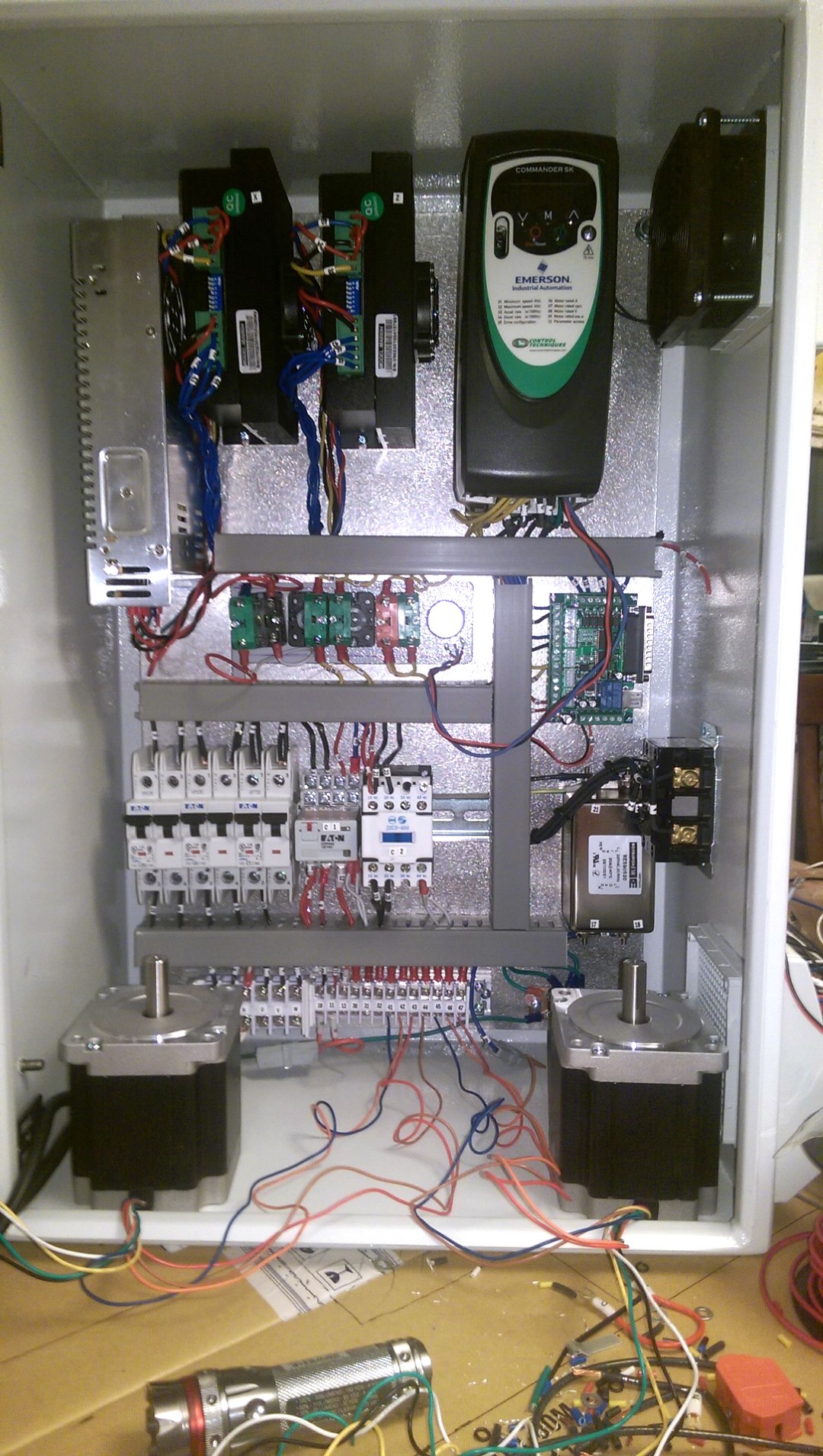
Modified lathe with new motor mounts ready for steppers.
.
Any CNC needs limit switches so the machine can find home position for each axis.
Mounting a limit switch.
Fortunately, when we dismantled the manual control box we found two momentary switches perfect for this purpose, so we mounted them in a convenient position for each drive screw.
For cabling you would normally have cable tracks, but we avoided this for the X-axis by simply allowing the wires going from the control box on the back to the X-axis driven from the front to hang loosely under the machine.
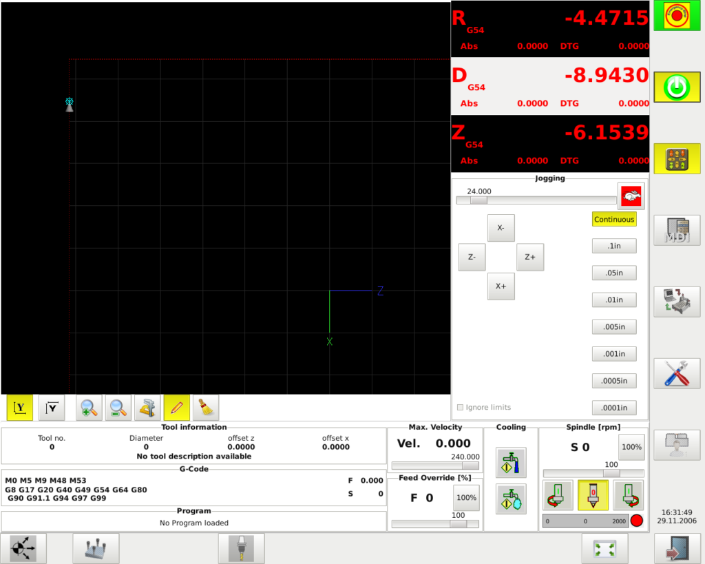
We now had a functional CNC lathe. LinuxCNC was working well, although the UI looked like an old Windows 98 app.
LinuxCNC screenshot (no program loaded until I figure out how to make it ignore the fact it’s not hooked up).
Fortunately, we found two alternate user interfaces after perusing their user forums, both of which looked and worked much better.
As is usual with Linux, be prepared to read lots of forums and documentation and to edit text files to get the configuration you need.
A jig for shaping and sharpening knife blades. Handles made on the CNC lathe!The final sharpening jig
Conclusion
We also plan the following future enhancements:
We lost the ability to cut threads with this project. However, LinuxCNC supports this if you can provide feedback from an optical spindle speed sensor.
Liquid coolant can be very useful, even on an uncovered lathe at low RPMs.
We can limit backlash by ordering new ball nuts where every fourth or fifth ball is a different size to tighten the tolerance between the ball screw and nut.
The ball screws need to be protected. We need to craft some covers or brushes to keep them clean.
VERN ADERMANN is CEO/founder of CityWide Co. and an engineer with 20-plus years’ experience in robotics and process systems in the semiconductor and aerospace industries.
When you buy through links on our site, we may earn an affiliate commission.
Our websites use cookies to improve your browsing experience. Some of these are essential for the basic functionalities of our websites. In addition, we use third-party cookies to help us analyze and understand usage. These will be stored in your browser only with your consent and you have the option to opt-out. Your choice here will be recorded for all Make.co Websites.
Allow Non-Necessary Cookies
Escape to an island of imagination + innovation as Maker Faire Bay Area returns for its 15th iteration!
Buy Tickets today! SAVE 15% and lock-in your preferred date(s).