When I wrote my new book Make: Minecraft for Makers, you know I had to include a monster Creeper project. Here’s how you can build a motorized Creeper, with a metal skeleton and wooden skin. Aside from the fact that this thing most certainly doesn’t blow up, you’ll love it, and you’ll learn a lot about robotics and Arduino along the way. Let’s get to it!

The Creeper consists of a robot chassis kit with add-on parts creating the mob’s distinctive armless body, with a servo motor to move the head around. Begin by taking a look at the Creeper in-game. Just be sure to stick to Creative mode or you may find yourself getting blown up!

The Creeper has a cubical head 8 pixels on a side, a 4×8×12 body, and four 4×8×4 legs. It’s actually a pretty elegant design, which makes it a breeze for building a physical re-creation.

DESIGN IT

The Robot Creeper seems super challenging at first. The thing has to look like a Creeper, ideally proportionate with the game element. At the same time, it also has to function as a robot. In other words, regardless of its outer appearance, the Creeper has to be able to fit all the necessary robotic components, particularly the chassis kit we’re using for the base.

I began with the Actobotics Bogie Runt Rover, a kit available for around $70 that comes with a chassis, six motors, and six wheels. The assembled rover’s chassis measures 6″×9″, though the wheels project a little, and it rides fairly high: 6″ off the ground. With those measurements I was able to decide the size of the footprint: 12″×8″ — conveniently, one inch per pixel.

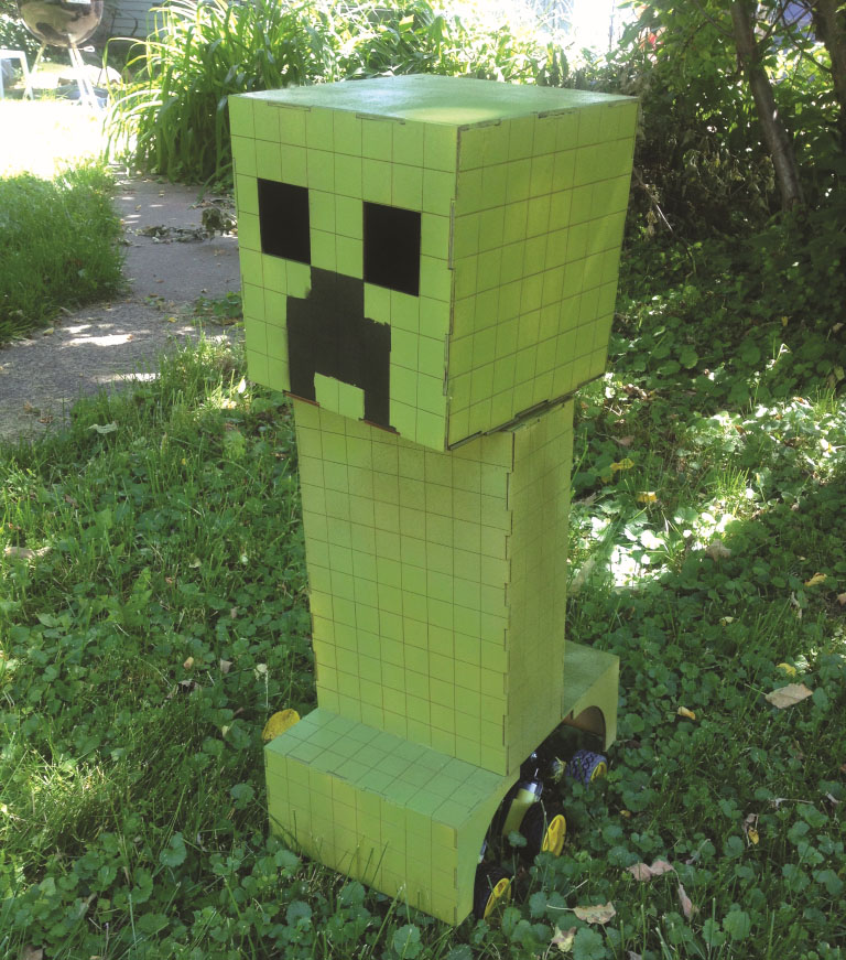
Applying the one-inch scale across the whole robot makes for a 12″-high, 8″-wide, and 4″-deep body, an 8″ cubical head, as well as four legs 6″×4″×4″. However, for the legs I decided to merge the front pair and back pair into 8″-wide blocks — the thing is going to roll, not walk. The image above shows my final design. I created vector files to be used on a laser cutter, but you could simply cut the pieces from wood, or get creative with other materials — recycle those Amazon boxes and use some packing tape to knock out a cheap, simplified version.

Next, we need to design the robot’s electronics. What will be its functionality? How will it be controlled? The Minecraft Creeper is known for blowing up, and clearly that was out. It also turns its head, and we can do that by putting a servo motor inside the body to turn our robot’s head. The Creeper also has eyes that turn red when it’s about to explode. That’s easy! We’ll put NeoPixel Jewels in the head.

Under the hood I stuck with the classic Arduino Uno, with a motor control shield sitting on top. This add-on board helps the Arduino manage the high voltages needed to run motors, and it simplifies controlling them.

Speaking of control, I’m making a basic controllerthat connects to the robot via a trio of wires.

Project Steps

1. ASSEMBLE THE ROVER KIT

Begin the build by tackling the Bogie Runt Rover kit. There’s a great assembly video here.

2. ADD THE BODY BASE

Attach one 3¾” piece of channel to the center set of mounting holes on the rover, using a large square screw plate and four screws added from the underside.

3. ATTACH THE HEAD SERVO

Use the standard servo plate to attach the servo motor to the channel. While you’re at it, you can attach the coupler that attaches the servo’s shaft to the D-rod.

4. ATTACH THE BODY CHANNEL

Secure the 9″ channel to the 3¾” piece you already attached. Use a dual screw plate as shown.

5. ADD THE SUPPORT BEAM

Attach the second 3¾” channel at the top of the 9″ piece using the second dual screw plate.

6. ATTACH THE BEARING

Attach the bearing so that it lines up with the servo’s shaft.

7. SECURE THE D-ROD

Thread the D-rod through the bearing and secure it in the servo’s coupler.

8. ASSEMBLE THE FEET AND BODY SKINS

The Creeper’s skin consists of a series of laser-cut wooden box shapes that rely on gravity to stay on the robot.. The skins are all made from ⅛” plywood, except the head base is ¼”.

You can find the blueprints among the downloads for my book in the Chapter 9 folder.

9. PAINT IT!

It’s time to paint the body and feet that delightful Creeper green. The image below shows my creation with one coat of paint.

10. ATTACH THE SKIN

Once the paint is dry, drop the skin down on the robot  with the 1/4″ rod projecting from the top. It should fit nicely without any problem.

11. ADD THE HEAD BASE

Use 1/4″ plywood, 8″×8″ square. Drill a 1/4″ center hole as well as the mounting holes for the setscrew hub; then secure the hub with the small square screw plate.

12. BUILD THE HEAD

Assemble the panels of the head. Once again, a plywood box! This one needs holes for eyes.

13. PAINT THE HEAD

Paint the outside of the head green to match the skin, but also add the black parts of the face. I suggest painting the inside of the head black so the eyes look blacker.

14. INSTALL THE ARDUINO

Find a spot on the underneath of the robot to install the Arduino using #4 hardware. You can drill into the Bogie’s ABS chassis if you want, or use one of the available mounting holes.

15. SEAT THE MOTOR SHIELD

The motor shield sits right on top of the Arduino, with the shield’s male headers plugged into the Arduino’s female headers.

16. CONNECT THE SERVO

Attach the servo wires to the motor shield’s Servo 1 pins.

17. MOUNT THE 9V BATTERY

Attach the 9V battery to the chassis but don’t plug it in yet. (the image shows it plugged in)This powers the Arduino but not the motors.

18. ATTACH THE BATTERY PACK

Attach the 4xAA battery pack to the chassis and plug it into the motor shield’s Power terminals, as shown.. This pack powers the motors separately.

19. CONNECT THE MOTORS

You have six motors, three on the left and three on the right. Combine the leads as you see in the image below, so that the M3 motor terminals control one side, and M4 controls the other. The Bogie’s motors are modest in size and stacking them won’t strain the motor shield’s capabilities.

20. WIRE UP THE NEOPIXEL EYES

You’re using two NeoPixel Jewels for eyes, to create the telltale glowing red that signals an imminent explosion. Connect both Jewels’ VIN (red wire) and GND (black) pins to the Arduino’s GND and 5V pins. The data wire goes from digital pin 6 on the Arduino to the IN pin on the first Jewel, and then from OUT to IN on the next eye.


21. WIRE THE CONTROLLER CONNECTIONS

You’ll need three wires to attach the Creeper to its controller. One wire connects to digital pin 0 on the Arduino, another to pin 1, and a third to GND. You’ll connect these to their counterparts on the controller’s Arduino. You can make these wires as long as you want, but 6′ is probably good enough.

22. PROGRAM THE CREEPER

The Creeper is a simple robot, and this is reflected in the code.

#include <Wire.h>

#include <Adafruit_MotorShield.h>

#include “utility/Adafruit_PWMServoDriver.h”

#include <Servo.h>

#include <Adafruit_NeoPixel.h>


Adafruit_MotorShield AFMS = Adafruit_MotorShield();

Adafruit_DCMotor *leftMotors = AFMS.getMotor(3);

Adafruit_DCMotor *rightMotors = AFMS.getMotor(4);

Servo servo1;


#define PIN 6

Adafruit_NeoPixel strip = Adafruit_NeoPixel(14, PIN, NEO_GRB + NEO_KHZ800);


const int buzzerPin = 13;


void setup()

{

Serial.begin(9600);

AFMS.begin();

servo1.attach(10);

strip.begin();

strip.show(); // Initialize all pixels to ‘off’

}


void loop() {

if (Serial.available() >= 2)

{

char start = Serial.read();

if (start != ‘*’)

{

return;

}

char cmd = Serial.read();

process_incoming_command(cmd);

}

delay(50); //limit how fast we update

}


void process_incoming_command(char cmd)

{

int speed = 0;

switch (cmd)

{

case 0:

//DO NOTHING

break;

case 1:

//DRIVE LEFT WHEELS

leftMotors->setSpeed(200);

leftMotors->run(RELEASE);

break;

case 2:

//DRIVE RIGHT WHEELS

rightMotors->setSpeed(200);

rightMotors->run(RELEASE);

break;

case 3:

//TURN ON EYES

strip.setPixelColor(0, 255, 0, 0);

strip.setPixelColor(1, 255, 0, 0);

strip.setPixelColor(2, 255, 0, 0);

strip.setPixelColor(3, 255, 0, 0);

strip.setPixelColor(4, 255, 0, 0);

strip.setPixelColor(5, 255, 0, 0);

strip.setPixelColor(6, 255, 0, 0);

strip.setPixelColor(7, 255, 0, 0);

strip.setPixelColor(8, 255, 0, 0);

strip.setPixelColor(9, 255, 0, 0);

strip.setPixelColor(10, 255, 0, 0);

strip.setPixelColor(11, 255, 0, 0);

strip.setPixelColor(12, 255, 0, 0);

strip.setPixelColor(13, 255, 0, 0);

strip.show();

break;

case 4:

//TURN OFF EYES

strip.setPixelColor(0, 0, 0, 0);

strip.setPixelColor(1, 0, 0, 0);

strip.setPixelColor(2, 0, 0, 0);

strip.setPixelColor(3, 0, 0, 0);

strip.setPixelColor(4, 0, 0, 0);

strip.setPixelColor(5, 0, 0, 0);

strip.setPixelColor(6, 0, 0, 0);

strip.setPixelColor(7, 0, 0, 0);

strip.setPixelColor(8, 0, 0, 0);

strip.setPixelColor(9, 0, 0, 0);

strip.setPixelColor(10, 0, 0, 0);

strip.setPixelColor(11, 0, 0, 0);

strip.setPixelColor(12, 0, 0, 0);

strip.setPixelColor(13, 0, 0, 0);

strip.show();

break;

case 5:

//TURN HEAD 90DEG LEFT

servo1.write(0);

delay(15);

break;

case 6:

//TURN HEAD 45DEG LEFT

servo1.write(45);

delay(15);

break;

case 7:

//TURN HEAD FORWARD

servo1.write(90);

delay(15);

break;

case 8:

//TURN HEAD 45DEG RIGHT

servo1.write(135);

delay(15);

break;

case 9:

//TURN HEAD 90DEG RIGHT

servo1.write(180);

delay(15);

break;

}

}

You can download this code file, creeper.ino, at Github in the Chapter 9 folder. Then open it in the Arduino IDE, and Upload it to the Arduino.

The sketch works by listening for commands from the controller via the serial connection, then activating the appropriate LEDs or motors. Of course you can modify the code to fine-tune your mob or give it new behaviors.

23. ASSEMBLE THE BOX

The controller I built is a simple plywood box 6″×4″×2″, and it fits nicely in my hand.

As usual, I’m including the vectors for my controller in with the downloads. I painted the box purple just for fun.

24. INSTALL THE ARDUINO

Use wood screws to attach the Arduino to the bottom of the controller box.

25. WIRE UP THE BUTTONS

Take the mini breadboard PCB and attach the two buttons and the switch that turns on the eyes. They all work the same way in Arduinoland. Connect one lead to power (shown as green wires in the image below  ). Connect the other leads (gray wires) to the Arduino digital pins 9 (switch) and 5 and 6 (buttons), and also to GND via a 10K resistor.

26. ATTACH THE POTENTIOMETER

The first lead connects to power, the third lead connects to GND, and the middle one to analog pin A0 on the Arduino. This image shows the pot wired up.

27. ADD BATTERY AND POWER SWITCH

The second switch controls power to the Arduino. Wire it in line with the 9V battery  — or skip it if your battery pack already has a switch.

28. INSTALL THE LED

Grab your RGB (tricolor) LED. Ignore the blue lead. Connect the red and green leads to digital pins 10 and 11, respectively, with 220-ohm resistors protecting the LED, and the common cathode to GND .

29. CONNECT TO THE ROBOT

Connect the three long wires from the robot to the same pins on the controller.

30. PROGRAM THE CONTROLLER

Download purple_controller.ino from the GitHub page and upload it to the Arduino.

GET CREEPIN’

Your mob is ready to go mobile. Press the arcade buttons to steer the robot base, while turning the head with the potentiometer. Now activate the robot’s menacing red eyes by flicking the switch!


This project is excerpted from Make: Minecraft for Makers,
available at makershed.com and other retailers.