vlcsnap-2015-07-30-14h43m03s148

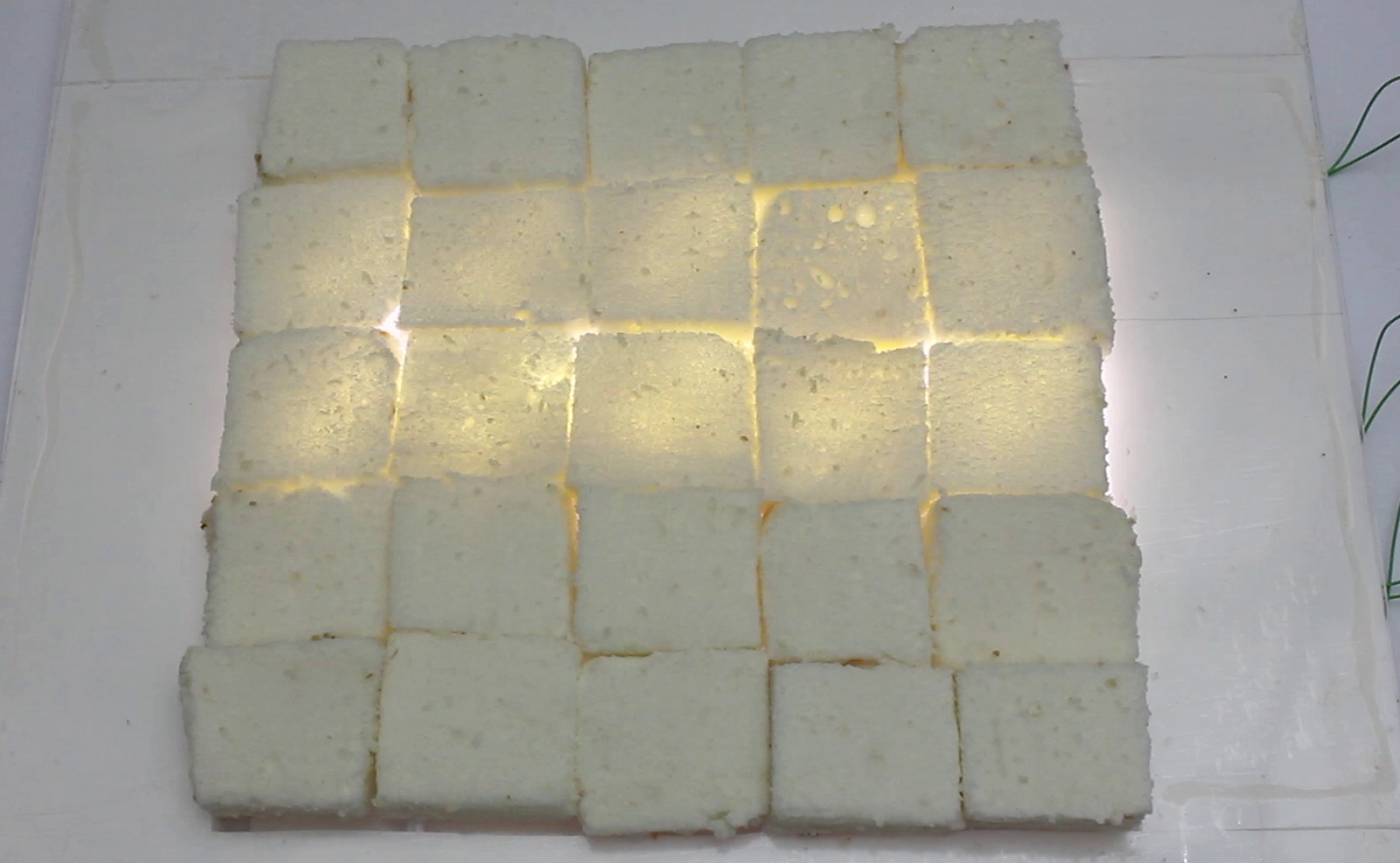
Everyone loves dessert, but you can make them even better by adding LEDs. By setting up an LED matrix under your dessert, you can make it light up and play animations. In this project, I am going to show you how to make a dessert tray with a built-in LED matrix that you can control with an Arduino.

YouTube player

Project Steps

Mark out a grid for the LED matrix

Take a large piece of white poster board or card stock and cut out a square that is 10″×10″. Then use a ruler to mark out a grid of smaller squares that are each 2″×2″. This should give you a total of 25 smaller squares in five rows and five columns. Each square will be one location in the LED matrix.

I will be using two LEDs in each square. To center them, I made two lines connecting opposite corners of the square. This marks the center of the square. I then just marked two locations evenly spaced from the center point.

Insert LEDs into the card stock

Mark the locations of each LED. Then use a pin to poke holes for each of the leads.

Insert the leads of the LEDs through the holes. Be careful to keep all the LEDs in the same orientation. You want all the cathodes going in the same direction and all the anodes going in the same direction. The easiest way to check this is to make sure that the flat edge is on the same side of each LED.

Connect each pair of LEDs in parallel

You want the LEDs in the same square to turn on and off together. So you need to wire them together so that they are connected in parallel. There are a lot of ways that you can do this. I bent all the cathodes in one direction and all the anodes in the opposite direction. Then I used small pieces of heat shrink tubing to bind them together.

Connect the anodes of each row together

Now we need to connect the individual squares together into rows and columns. First we will connect the anodes in each row together. Start by bending the ends of the anode wires so that they are running parallel with the row. Then take a long bare wire and using small pieces of heat shrink tubing attach this wire to the anodes. After attaching the wire to the anode leads, place a long strip of tape over each row to help insulate it.

Connect the cathodes of each column together

Now you need to connect the cathodes of each column together. Bend each of the cathode leads so that they are parallel with the columns. Then take a long bare wire and using small pieces of heat shrink tubing attach this wire to the cathodes. After attaching the wire to the cathode leads, place a long strip of tape over each column to help insulate it.

Test the LED Matrix

Now that you have assembled the LED matrix, you need to test it to make sure that all the LEDs are properly connected. The easiest way to do this is with a 3V battery pack. Connect the positive wire of the battery pack to one of the anode rows. Then connect the negative wire of the battery pack to one of the cathode columns. This will connect power to the LEDs that are in the square that is at the intersection of this row and this column. If the wires are connected properly, these LEDs should light up. Repeat this test with every row and every column in sequence until you have tested all 25 squares.

Add paper dividers between each square

In order to keep the light from each square from diffusing over into the adjacent squares, I added a paper divider between each set of lights. This was just a simple folded piece of white paper that I taped in place.

Construct the plexiglass cover

Now you need to construct the plastic cover plate. This will serve as a surface for the dessert to be displayed on and it will protect the electronics.

I started with a 16″×16″ sheet of plexiglass. Then I cut several pieces of 1/8″ foam board to make the sides of the stand. I cut four pieces that were 3″×16″ and four pieces that were 3″×10″. I used hot glue to attach these in two layers around the outside of the plastic. Try to keep the hot glue as close to the edge as possible so that it isn’t as visible.

Construct a transistor switching circuit to control the LED matrix

The simplest way to control the LEDs would be to connect them directly to the digital pins. You would activate each LED by sending a HIGH signal to the anode (rows) and a low signal to the cathode (columns). This would turn on the corresponding LED.

However, each digital pin can only output a maximum of 40mA. This was not enough to power the LEDs that I am using. So I made a transistor switching circuit that could handle much more current.

This transistor circuit has an NPN power transistor connected to each set of cathodes and a PNP power transistor connected to each set of rows. In this configuration you would activate an LED by sending a HIGH signal to the base of the NPN transistor and a LOW signal to the base of the PNP transistor. 1 kohm resistors are attached to the base of each transistor to limit the base current. Series resistors are also added to each LED to bring the 5V signal from the digital pin down to the voltage of the LEDs.

Upload code to the Arduino

Now all that is left is to connect the transistor circuit to your Arduino and upload some code.

In many cases you will want to use a process called multiplexing. This is where a series of individual LEDs are turned on and off in sequence so rapidly that they appear to all be on at the same time. This is necessary because of the way that the LEDs are addressed by the row and column.

Finished!

Now your LED matrix dessert tray is complete. All you need to do is add your favorite dessert. Use a dessert that lets a lot of light pass through it, for example, white cakes such as angel food cake work very well. If you want to use frosting, stick to light colored frosting and keep the frosting thin. You can also use things like rice crispy treats.

This light-up dessert tray is a great way to add some fun to parties or any event where food is served.

Here are some sample LED patterns for testing your fancy new dessert tray:
1, 2, 3, 4, 5