Luminous_Lowtops1H1A8302

YouTube player

The light-up shoes from your childhood are all grown up — these Luminous Lowtops are force-sensitive, full-color LED light-up shoes for adults. Each shoe has two embedded force-sensitive resistors (FSRs) — one under the heel and one under the ball of the foot — and up to 40 RGB LEDs that change color based on the FSR readings, giving brilliant visual effects when you walk, stomp, jump, or lean.

Not long ago I saw a little boy stomping around a store in his light-up shoes. Admittedly jealous, I searched online for adult light-up shoes. Disappointingly, none of them responded to how you moved, only to the fact that you moved. Also, most of them required a battery pack to be strapped to the leg or shoe, rather than putting it inside like the kids’ shoes do. With those issues in mind, I decided to make the Luminous Lowtops.

The electronics are as simple as possible, to allow everything to fit within the shoe. The LEDs are individually addressable, so each one can be a different color at the same time, allowing the shoes to show shifts in weight and react to your movements. An Arduino Mini microcontroller reads an analog input from the front and rear FSRs, converts these values into colors and maps them to the front and rear LEDs, then calculates a color gradient for all the LEDs in between.

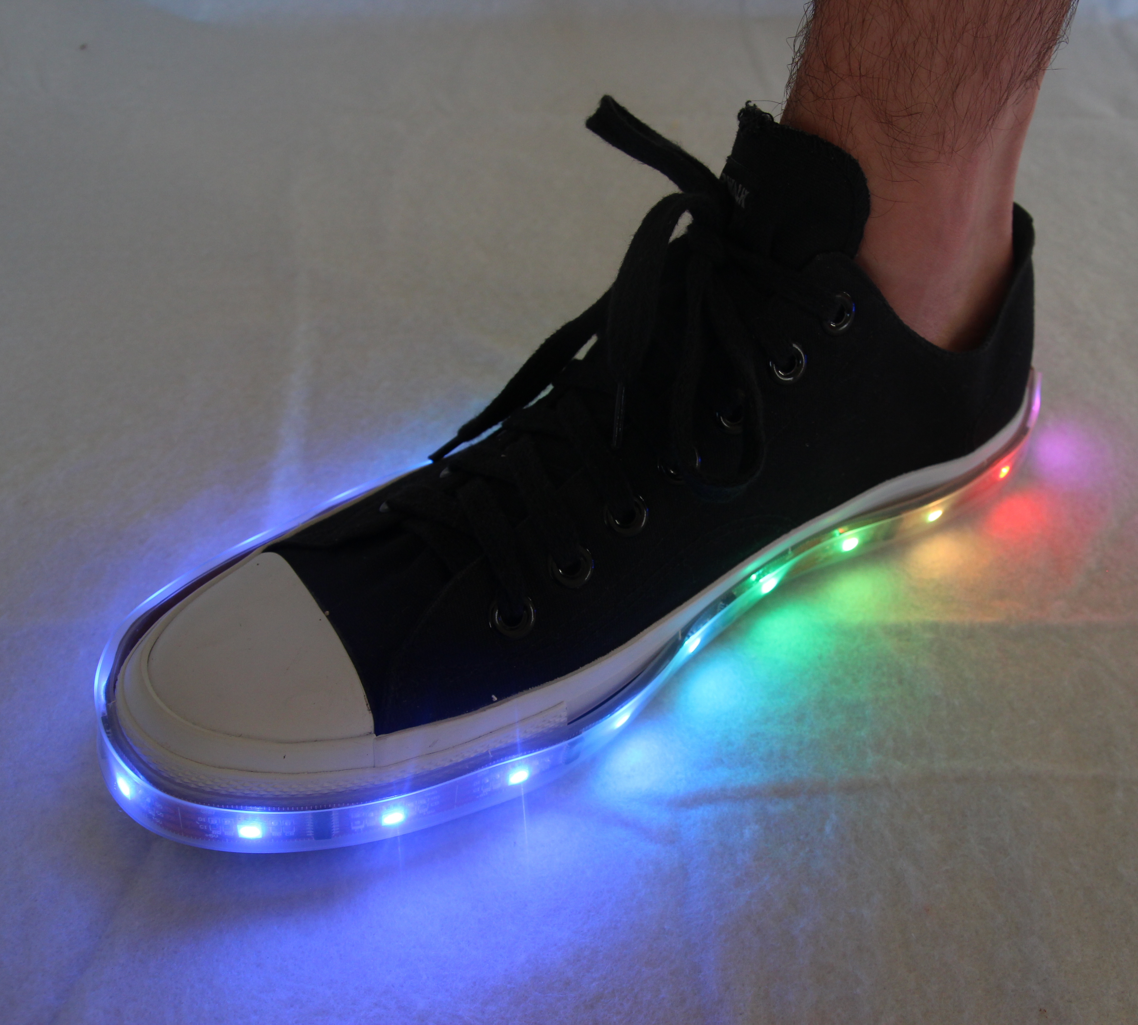
Each shoe is powered by 3 rechargeable AA batteries under the heel, and the components are embedded under the insole for a clean look. The LED strip is securely sewn to the exterior of the shoe, so you can jump, dance, or just gaze at the changing colors.

Project Steps

Gather materials.

Here’s what you’ll need. Top row (left to right): shoes, LED strip, sewing kit, rotary tool, wire strippers, wire. Bottom row (left to right): FTDI Basic Breakout board, Arduino Pro Minis, 1MΩ resistors, force sensor, battery pack, cotton padding, tape, NiZn batteries, NiZn battery charger.

You also need a soldering iron and solder (not pictured).

Prepare the shoes.

There are two good mounting options for the batteries and Arduino. Mounting them on top of the tongue of the shoe is easier, but they’ll be more visible. If you really want to hide the components, try putting them inside the shoe under your heel.

If you’re mounting these components inside, choose shoes with a thick insole. This allows for some of the padding to be cut out and replaced with the 3xAA battery pack. Rip out the insoles and strip all extra padding off of them, leaving just a thin layer of padding.

Save the padding; you might like to replace some of it later for comfort.

Attach the LEDs.

Using scissors, cut the LED strips to the proper length to wrap around the perimeter of each shoe. The SparkFun and NeoPixel strips can be cut between any 2 LEDs (just avoid cutting the copper contacts); the Adafruit #306 strips must be cut between along the lines that appear after every second LED.

Using a needle and thread that matches your shoes, sew the LED strip to the shoe. To do this, loop the thread from the inside of the shoe, out through edge of the LED strip, and back through the opposite edge of the strip and into the shoe. Pull this loop tight and tie a knot.

Repeat this process about once every inch along the shoe’s perimeter.

Drill the shoes for wire access.

Drill a small hole through the back of each shoe, under the insole. This will allow wires from the Arduino and battery pack to reach the LED strips.

Build the circuit.

Following the wiring diagram, solder together the circuit for each shoe.

The wires from the Arduino to the LED strips need to be about half the length of the shoe; the wires to the force sensors should be about three-quarters the length of the shoe. Cut them longer than you think you need; you can always shorten them if necessary.

Don’t solder directly to the force sensors, as they are plastic and could melt. Instead, solder to a 3-pin block of female header, and then plug the force sensor into the header. (The middle pin of the force sensors is not used.)

While you’re at it, solder the included headers to the FTDI breakout board.

Program the Arduino.

Download the project code and open it in the Arduino IDE:

» If you’re using the SparkFun or NeoPixel LEDs, grab the Neopixel.ino project code here and make sure you also get Adafruit’s Arduino library for NeoPixel LED strips here.

» If you’re using the Adafruit #306 LEDs, get the 8806.ino project code here and get Adafruit’s library for LPD8806 PWM LED strips here.

Under the Tools –> Board menu, choose Arduino Mini w/ATmega328. Also, under Tools –> Serial Port, select the serial port that your board is plugged into.

Plug the FTDI breakout board header pins into the corresponding 6 pins on the end of the Arduino Pro Mini.

Count the number of LEDs on your shoe, and edit the line int nLEDs = 40; in the code to reflect your number. Then click Upload in the Arduino IDE. Unplug the Arduino board.

Repeat for the second Arduino Mini.

Mount the force sensors.

Use duct tape or packing tape to mount the force sensors inside the shoe, on top of the sole (so they’ll be under the footbed or insole). Place them so that the circular pad of one force sensor is under the ball of your foot and the circular pad of the other is under your heel.

Run the wires and resistors flat along the bottom of the inside of the shoe.

Mount the battery pack and Arduino.

Tape the battery pack on top of the heel force sensor, so that it fits comfortably under your heel. I rip out any extra padding under the heel first. Most shoes have a hard pad under the heel to lift it; the battery pack essentially replaces this.

The Arduino should lie flat, forward of the battery pack (toward the arch of the foot), but tucked close to the battery pack so that the batteries take the weight of your foot, not the Arduino. Cover it with a bit of cotton padding or a cotton ball to protect it and to prevent it from poking you. Once you’re sure the shoes are working great, you can seal the Arduino in with hot glue, or stash it in an empty 2xAAA battery pack.

Replace the insole to cover the electronics and battery pack. Though you’ve thinned it out, it still offers a bit of a cushion.

If your shoes don’t have room for these components under your heel, mount them on top of the tongue, behind the point where the tongue flexes. Again, protected our Arduino by hiding it in an empty 2xAAA battery pack.

Power up the shoes.

Charge the six NiZn AA batteries and place them in the battery pack of each shoe.

Put the shoes on, lace them up, and watch as they react to how you walk, run, jump, and dance!

What's the code doing?

The project code is well commented so you can follow what it’s doing. The basic code loop reads an analog input from the front and rear force sensors (their resistance changes linearly with the amount of force, and they’re connected to the Arduino with pull-down resistors). It then takes those force values and scales them to the color space of the LEDs based on some general estimates of the maximum and minimum resistances of the force sensors.

Once the code has calculated the corresponding colors for the front LEDs and the rear LEDs, a for loop produces a color gradient of sorts for all the LEDs in between.

Finally, the code sends these color values to the individual LEDs.

Possible modifications.

To improve the fit with the components mounted inside the shoe, try excavating a cavity in the top of the sole to accept the battery pack. Or move the batteries and Arduino permanently to the top of the tongue of the shoe.

To protect the Arduino from friction and flexure, wherever you mount it, try stashing it in an empty 2xAAA battery pack.

Try modifying the getColorFromForce function in the code so that the default color (with no weight on the sensors) is your favorite color.

Apply the techniques and code from this project to modify a different kind of shoes, like these light-up high heels.