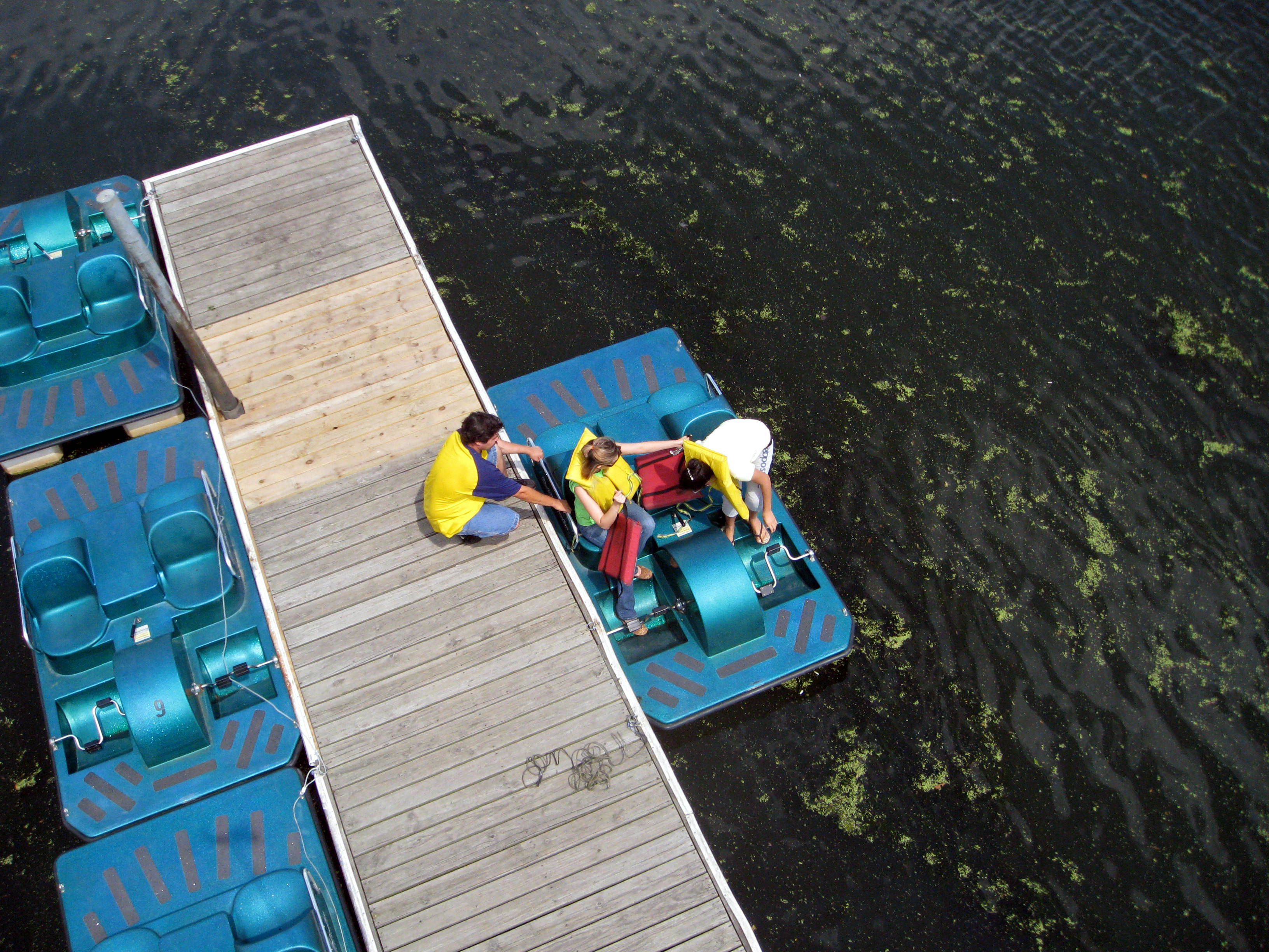
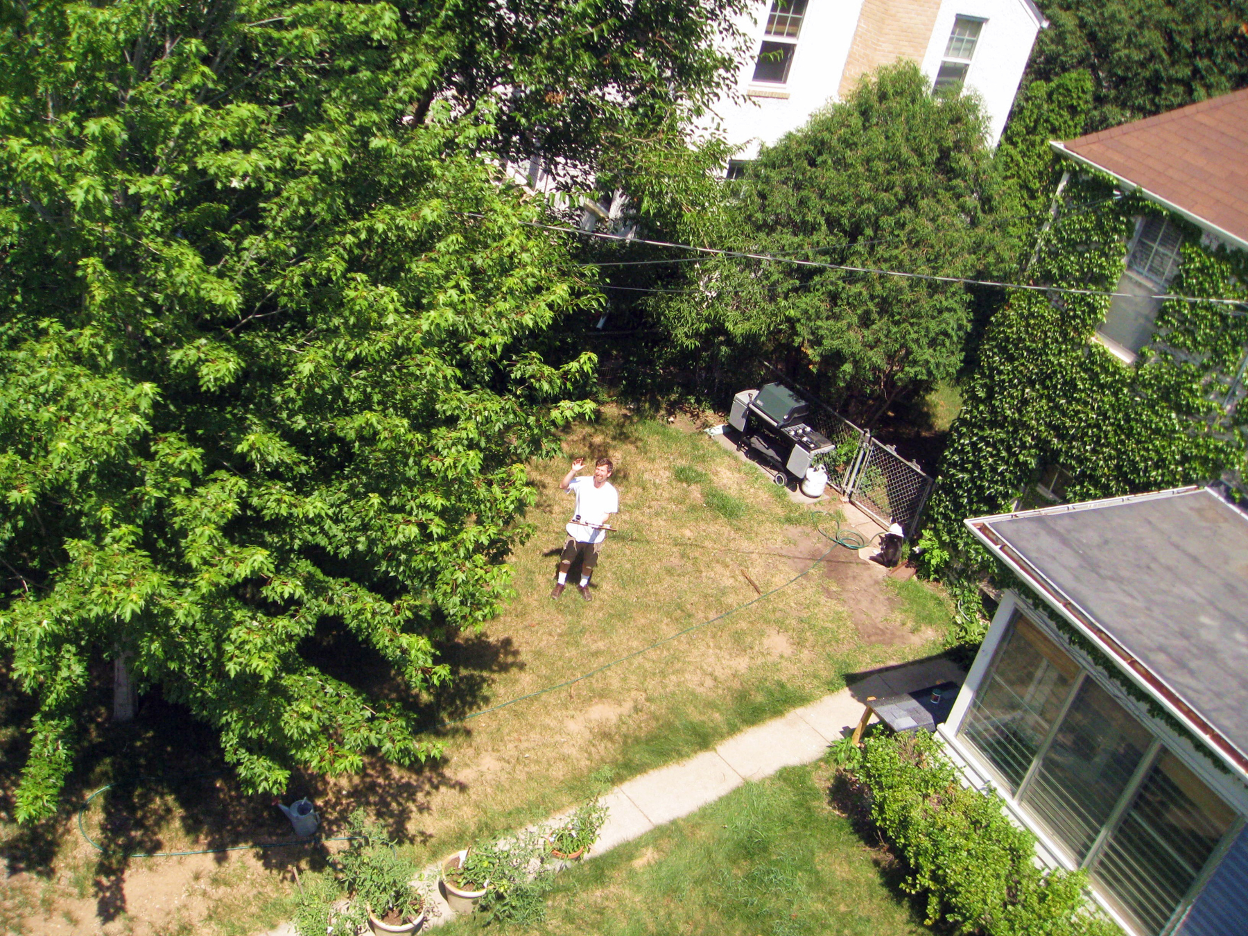
Sometimes nothing is as important as perspective. My goal in photography is often to find a view no one else has found, to be able to see things from unusual and insightful vantage points.

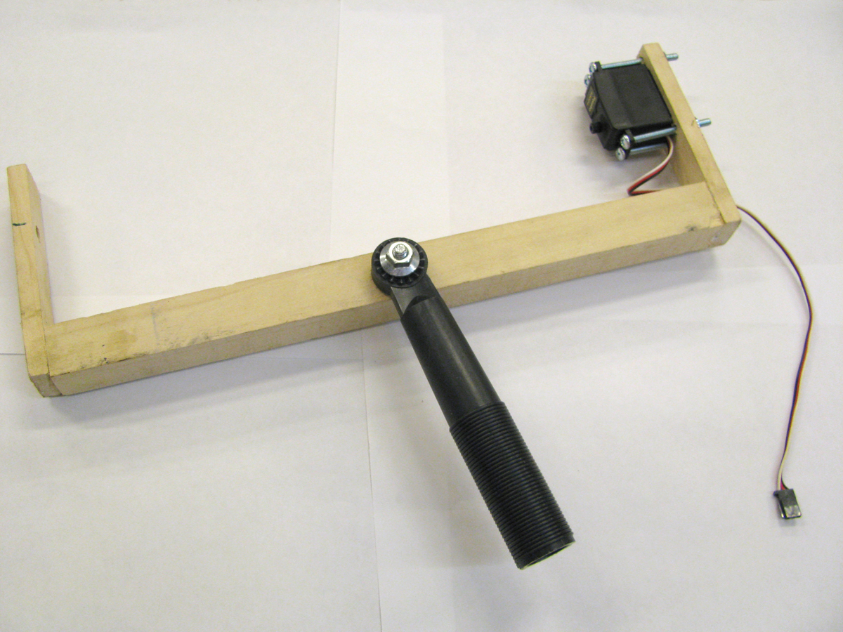
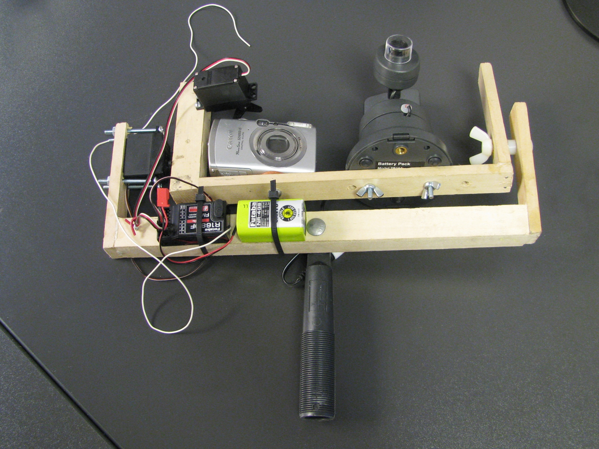
The most practical way to obtain the elusive aerial perspective is by attaching a camera to a mast. While not trivial, it’s not complicated, either. Making a mast-mounted camera rig like the Sky Eye takes about a day, not including trips to the store. You can make the rig and use it the same day.

I’ve experimented many times with aerial photographic techniques for obtaining the much-sought-after bird’s-eye view. First, there was the specially rigged kite, way back in the first issue of MAKE (Volume 01, page 50, “Kite Aerial Photography”). And I’ve dabbled with taking pictures from R/C aircraft, helium balloons, model rockets, and so forth.

While these approaches are novel, I find them limiting because the photographer is at the mercy of uncontrollable factors. There may be too much wind to loft a balloon, or not enough to fly a kite. Rough terrain or low visibility may make it impossible to launch and recover a rocket-borne camera. And none of these methods works indoors, say at a stadium. The Sky Eye works in all these conditions.

Project Steps

Measure the camera and servomotors.

After you’ve gathered your materials, the first step is to size up your camera and servos with a ruler and record the following dimensions:

A. The distance from the end of the camera to the center of the shutter button.

B. The distance from the end of the camera to the center of the tripod socket.

C. The height of the camera, from the camera bottom to the top of the shutter button.

D. If you choose to include the wireless video camera viewfinder, measure and record the overall width and height of the video camera.

E. The distance from the center of the servo arm to the servo mounting holes.

F. The distance from the center of the servo arm to its tip.

Build the frames.

Using the wood framing dimensions from the Materials list, build the camera-holding top frame (shown at the top of the photo), using glue and nails. You can use wood screws, dowels, or pegs instead of nails if you prefer.

Next, build the mast attachment, or bottom, frame (shown at the bottom of the photo).

Mount the shutter servo and camera(s) to the top frame.

Mount the shutter servo to the left upright of the top frame (the 1″×1″ piece). Position it so that its centerline is at a height of (C + F + 2 washers) above the surface of the base piece where the camera will be mounted, i.e. the combined length of the camera height (C) plus the length of the servo arm (F) plus the thickness of 2 hose washers.

Drill 2 holes in the upright with a #25 drill bit (about 5/32″), corresponding to dimension E. Attach the shutter servo to the upright with two #6 machine screws, and fasten it securely with nuts.

Drill a ¼”-diameter clearance hole in the base for the camera-mounting machine screw, at a position such that the shutter button is directly underneath the servo arm when the arm is fully extended. This distance varies between cameras and depends on both dimensions A and B.

Insert the 1″-long, ¼”-diameter machine screw into the camera-mounting hole on the top frame. Place a few hose washers over this bolt before securing the camera. As you tighten the camera by turning the machine screw, the hose washers compress; this will give you a degree of fine adjustment of the shutter servo in a subsequent step.

Once you’ve successfully positioned the servo arm, the shutter will trip each time the servomotor rotates.

(Optional) If you’re going to add the wireless video camera, drill mounting holes for it on the top frame, corresponding to dimension D, then attach it with two #8 machine screws, nuts, and lock washers. Take care to align the digital and video cameras so that they point at the same target.

Mount the tilt servo and radio gear to the bottom frame.

Mount the tilt servo to the bottom frame, as shown here, using four 2″-long #6 machine screws. Install the nylon bolt, spacer, and nut on the bottom frame exactly opposite the tilt servo’s axis of rotation. Take time to carefully align this axis so the servo can easily and smoothly control the tilt angle. Attach the tilt servo’s control arm to the top frame with very small wood screws or wire brads.

Attach the paintbrush extension to the bottom frame using a ¼”-diameter, 2″-long carriage bolt.

Then attach the radio control receiver and the receiver/servo battery pack to the bottom frame using cable ties. Pull the cable ties tight so the components can’t come loose.

Mount the frame to the pole.

The last task is to screw the brush extension into the pole. The qualities that make a good mast photography pole are light weight, stiffness, and strength.

I used a 23′ telescoping extension pole with the delightfully descriptive name of Mr. Longarm. Available in the paint department of hardware stores, it’s not expensive and works adequately, although it does flex quite a bit. Fully extended in a stiff wind, you’ll really feel Mr. Longarm’s sway. More intrepid makers may want to experiment with chromoly steel or carbon fiber poles.

Use your eye in the sky.

Plug all servomotors and batteries into the slots on the radio receiver. If you don’t know how to operate an R/C radio, read the manual, talk with a knowledgeable friend, or visit a model/hobby store.

Turn on the R/C transmitter and operate the levers to see which one controls the tilt servo and which one controls the shutter servo. Depending on your preferences, you may want to rearrange the servo plugs on the receiver. I plugged the tilt servo into radio channel 1 and the shutter servo into channel 3, thereby putting the tilt action and the shutter release on different joysticks.

Now you’re ready to take pictures. Turn on the camera and extend the pole to a reasonable height. Raising and lowering the pole can be a bit dicey with the camera mounted to the end. Work slowly and deliberately.

Mast photography is best done by 2 or more people: 1 to operate the camera shutter and tilt controls and (at least) 1 assistant to hold the mast or pole. To take pictures, the assistant rotates the pole so the lens faces the desired direction, and then the camera operator adjusts the tilt servo so that from the ground it appears that the lens is pointing directly at the item to be photographed. If you’ve equipped your rig with the wireless video viewfinder, frame the picture using the image on the television.

The camera operator then holds down the shutter joystick until the servomotor arm depresses the camera’s shutter button. If the servo fails to operate the shutter, readjust the tightness and alignment of the bolt that holds the camera against the top frame and washers.

Take safety precautions.

Tipping: The farther the pole is extended, the greater the tendency to tip and fall. Use extreme caution. Also, the greater the angle of tilt, the greater the tipping tendency. Hold the pole as close to 90° vertical as possible.

Buckling: Depending on the strength of the pole, the weight concentrated on the end of the pole could cause it to buckle or fold, especially when the pole is fully extended. The tendency to buckle becomes more pronounced as the pole is held at increasing angles from vertical. Test the strength of the pole before fully extending it or holding it at an angle.

Keep the camera and pole under control at all times, and most importantly, away from overhead wires and power lines.

Conclusion

This project first appeared in MAKE Volume 16, page 106.