Adapt10

For more on microcontrollers and wearables, check out Make: Volume 43.  Don't have this issue? Get it in the Maker Shed.
For more on microcontrollers and wearables, check out Make: Volume 43.
Don’t have this issue? Get it in the Maker Shed.

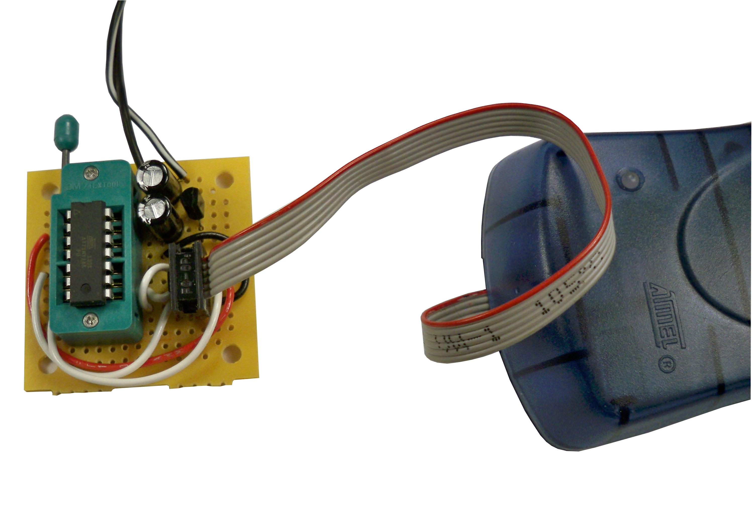
It’s really easy to program AVR microcontroller chips — but some of them don’t fit the standard Atmel programmer. For example, an adapter is needed to connect the Atmel ISPMKII programmer to an ATtiny24 microcontroller Dual Inline Package (DIP) chip. You can easily make this adapter with just a few components. In this example I use a Zero Insertion Force (ZIF) socket but a standard 14-pin socket can be used also.

The schematic for the adapter is shown here (click on it for a larger version). If you have a reliable source of 5 volts then you can leave out C2 and U1. You would then just connect your 5 volts directly to U2 pin 1.

ATtiny24adaptor

This tutorial covers the hardware aspects of programming an Atmel ATtiny24 microcontroller. For the software requirements, see my tutorial on how to build an Infrared Shooting Gallery, here.

Project Steps

Mount the components

Mount the components to the prototyping board as shown here.

Solder the component wires as shown on the bottom of the board. Note the component designations here and on the schematic (U1, U2, etc.).

Wire power and ground

Connect the ISP connector’s pin 2 to the IC socket’s pin 1 (power, red wire) .

Connect the ISP connector’s pin 6 to the negative (–) side of capacitor C2 (ground, black wire).

Wire the signal connections

Wire the RESET signal from the ISP connector’s pin 5 to the IC socket’s pin 4.

Wire the MOSI signal from the ISP connector’s pin 4 to the IC socket’s pin 7.

Wire the clock signal (SCK) from the ISP connector’s pin 3 to the IC socket’s pin 9.

Wire the signal connections, cont'd

Wire the MISO signal from the ISP connector’s pin 1 to the IC socket’s pin 8.

Connect power supply

Connect the power supply to the prototyping board at C2, as shown in the schematic. This completes the programming adapter.

NOTE: You can enhance the adapter by adding an on-off switch in series with the power supply, installing an LED to indicate power is on, and inserting standoffs in the mounting holes.

Connect your Atmel programmer

Connect the Atmel programmer and insert an ATtiny24 into the socket. Be careful to insert the ATtiny24 in the correct orientation, with its notch closest to the socket lever.

Connect power and program your microcontroller!

For more about the software you need to program your ATtiny24, see my tutorial on how to build an Infrared Shooting Gallery, here.