Thero-1

At my hackerspace, i3 Detroit, we have programmable thermostats that frustratingly reset your settings at fixed times. At home, our old thermostats just have a setting lever, and our power company has started time-of-day metering. So I decided to replace the thermostats at both i3 and home with smarter, programmable, networked versions.

Standard forced-air HVAC systems are surprisingly easy to control. The standard thermostat cable in the walls contains color-coded wires with the following functions:

R — Red — 24VAC power
Y — Yellow — Cooling
W — White — Heating
G — Green — Fan
C — Black — Common/ground, optional

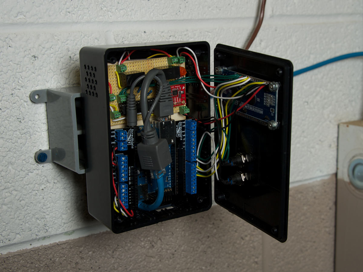
The 24V AC power comes from a 5:1 transformer at the furnace. To turn on the cooling, heating, or fan, you simply connect power (R) to the corresponding wire, Y, W, or G. If you program an internet-connected micro-controller to drive relays that switch these connections, then you have full local and networked control over these functions, and it can respond to data captured online.

You may find Rh and Rc wires (hopefully labeled with stickers) instead of an R wire. These are heating- and cooling-specific power sources that should connect to the W and Y wires separately. The fan wire lets you switch the fan manually at any time, and a standard HVAC system also automatically turns the fan on when needed for heating and cooling.

NOTE: If you have a dual-stage furnace or a heat-pump system, or if you find additional or different wire colors, you’ll need to do more research into your installation. The basic control scheme will be the same as described here, but the logic may be more complicated and include restrictions.


This article first appeared in MAKE Volume 30, page 54.

Project Steps

DESIGN OVERVIEW

The Arduino has a limited number of pins, so I used the I2C protocol to control the 24V relays that switch the system’s heating and cooling. I could’ve driven these 2 circuits from dedicated Arduino pins, but the I2C protocol lets you control multiple devices with just 2 wires, which means I can add more devices to my system, like for fan control or a heat pump/dual stage HVAC, without needing more Arduino output pins. Conveniently, an Arduino I2C library lets you run I2C’s 2 wires, Serial Data Line (SDA) and Serial Clock Line (SCL), off analog pins 4 and 5, and make easy program calls to each device.

I2C runs multiple devices off its 2 shared wires by giving each a unique address. Components designed specifically for I2C have jumpers or switches that configure this address, and you can give I2C addresses to simple, switchable devices (like my heating and cooling relays) by using an I/O expander chip like the MCP23017-E/SP. The protocol’s SDA and SCL lines connect to one side of this chip, and each device connects to one of 8 control lines (GPA0–GPA7) on the other side.

To enable time-based thermostat controls, I included an I2C real-time clock (RTC) module, which carries a DS1307 RTC chip and a lithium battery that can supposedly power it for 9+ years. To simplify the hardware, you could omit the RTC module and use the Ethernet interface to fetch the time, although this would give coarser time resolution.

Thero-A

Thero-B

To carry the I/O expander, relay circuits, and RTC, I built an Expander Board, and used screw terminals for all the external connections.

Thero-C

Of course, a thermostat needs a temperature sensor. I used a Sensirion SHT11 2-wire combination thermometer and humidistat connected to Arduino digital I/O pins 2 and 3. You can mount this on the Expander Board, but I left it dangling on wire leads for better mounting in the project box.

Instead of using separate cables to connect power and Ethernet from my DC transformer and router to the thermostat, I used a Power over Ethernet (PoE) cable set that “injects” both into one CAT5 Ethernet cable, then splits them back apart at the other end.

LOCAL CONTROL

Thero-D

The thermostat is controllable over the network, but 2 buttons and a small LCD also support local control, like a traditional thermo-stat. The buttons set the target temperature up and down, and the screen displays the current setting. The schematic above shows how these components connect, along with the Arduino and Expander Board. You can omit the buttons and screen to make the project simpler, and for any programming, such as time-based control, you’ll use the network interface.

Thero-E

For the screen, I used a 16×2-character LCD and followed Adafruit’s great tutorial on how to control these with an Arduino (ladyada.net/learn/lcd/charlcd.html). My only deviation was moving the Arduino digital pin connections from pins 7–12 to pins 4–9, because the Ethernet Shield needs pins 10–13. To prepare the LCD board, solder long wires onto its back for each connection needed, and mount the separate screen contrast trimpot on the Expander Board.

CONSTRUCTION AND INSTALLATION

Thero-F

Cut a plywood mounting plate to fit your box, then drill and screw-mount it inside, and mount the Arduino using #4-40 hardware and spacers. This project fits tightly in the 6″×4″×2″ box, so plan carefully where each item will go, to ensure that they won’t interfere with each other.

Thero-G

Using a drill and Dremel, cut holes for the LCD screen and up/down buttons in the box’s faceplate; ports for the HVAC control wires, PoE cable, and FTDI programmer in the sides; ventilation holes in the bottom and sides; and mounting holes in the back.

Thero-H

Mount the buttons and screen, adding spacers if needed to make the screen flush with the faceplate. Using the Arduino/LCD/SHT11/Expander Board schematic as a guide, wire up all components.

Thero-I

To enable secure wire connections without soldering, I plugged a ScrewShield into the Arduino. I mounted the Expander Board over the Arduino, and wired the mounting plate and faceplate components together like a book. The power regulator and other components in the box produce heat, so I tucked the temperature sensor into the bottom of the box, against the bottom ventilation holes. You can also drill a hole for the wires and put the sensor outside the box.

Mount the box to the wall; you can use small drywall anchors or attach it to an electrical junction box. Connect the HVAC wires to the Expander Board as shown in the Arduino/LCD/SHT11/Expander Board schematic. You can cut off any unused wires or tape them back, making sure they can’t contact anything in the box.

Thero-J

Connect the PoE cable pair’s “splitter” to the Arduino’s power and Ethernet jacks, route it out its hole, and connect it via CAT5 cable to the “injector” cable connected to power and Ethernet. Making sure all the parts are in place and have clearance, close the lid, and screw it on.

NETWORK SETUP AND SOFTWARE CONTROL

Download the project code zip file and follow the instructions to upload Make_Thermostat to your Arduino. The code supports the thermostat’s buttons and screen and also creates a web interface that displays the current and target temperatures and also lets you change the target.

This is accomplished in 2 parallel ways. For control within your home network, the code runs a simple web server at its IP address, which you can see by holding down both buttons. For control via the open web, the code reads and writes values to a server location, for access by a make_remote.php page (also in the project code zip file) on your home or remote server. This method enables multiple Arduinos to sync up, and also lets you save and change states while the Arduino is off. (The code’s local-only web server is for people who don’t have a server that runs PHP and MySQL; it’s also faster and more reliable if there’s outside network trouble.)

The Make_Thermostat code uses closed-loop feedback to maintain the temperature within a plus-or-minus “deadband” around the target. A larger deadband will cause the furnace to run less frequently but longer, creating more noticeable swings. A more complicated scheme is proportional-integral-derivative (PID) control, which uses learned or hard-coded information about the HVAC system to avoid overshooting the target.

You can of course modify the code to do anything you want, including learn your habits, learn PID values, and incorporate inputs from the clock or additional sensors. But to avoid damage to your HVAC system, you should avoid “short cycling” (running frequently in short bursts), and to protect your air conditioner compressor, cooling should be off for at least 5 minutes between runs.

Conclusion

This article appeared in MAKE Volume 30, page 54.