Glen A. Larson could be considered an American hero. He is the television producer responsible for bringing such gems as Battlestar Galactica and Knight Rider to the small screen. He has also displayed a fondness for red lights that scan back and forth, which featured prominently in the aforementioned shows. The Larson Scanner, named in his honor, is a circuit that lights LEDs in a sequence like the ones he used. Use it for your costume, bike, R/C car, case mod, or — as we did — the Cylon jack-o’-lantern.
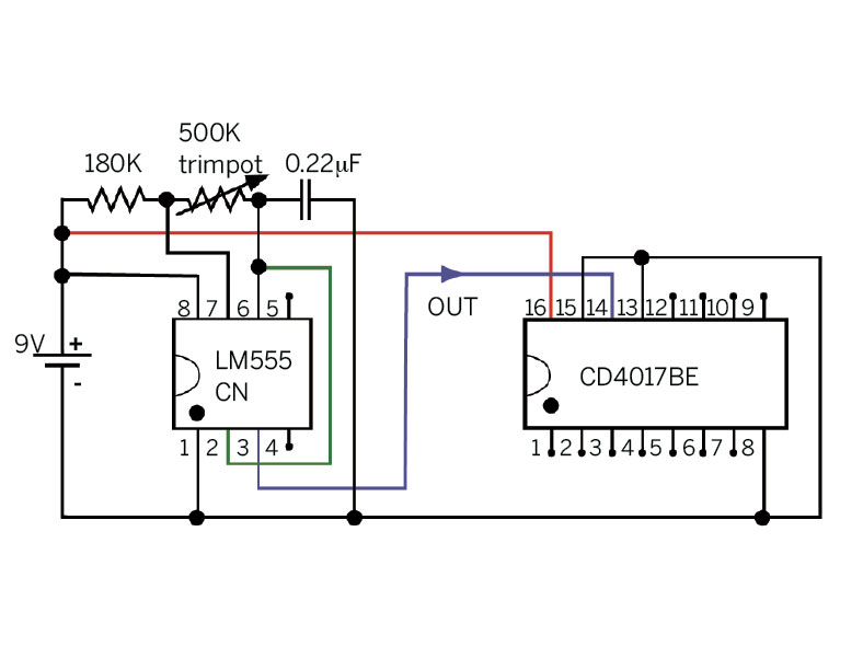
Our circuit features 2 chips: a 555 timer and a 4017 decade counter. The 555 is a handy building block for all manner of circuits. (See Make: Volume 10, page 62, “The Biggest Little Chip” by Charles Platt.) Our 555 is configured as an oscillator that outputs regularly spaced pulses at a rate controlled by a trimpot.

woom-woom!
Its output signal is connected to the input of the 4017 counter chip. The counter chip has 10 outputs (numbered 1 through 10), one of which is on at any given time. If 10 LEDs were driven by the chip’s outputs, you would see them light up in sequence from 1 to 10 and repeat as it receives a train of incoming clock pulses.
However, we want our LEDs to scan back and forth, not move in one direction repeatedly. We accomplish this by “folding” the 10 outputs back onto themselves so that if we had 10 LEDs, numbers 2 and 10 would be in the same location. Rather than using 2 LEDs in each location, we use 1, and so only 6 LEDs are needed. As the counter counts from 1 to 6, the 6 LEDs light up in sequence. Then, as the counter finishes counting from 7 to 10, the middle 4 LEDs light up in the reverse sequence. This gives the illusion of an LED that moves continuously from one end to the other and repeats. Since the middle 4 LEDs will be lit up when either of 2 counter outputs is on, we use simple diode OR gates to allow this logical control.
The final detail, not to be neglected, is that high-brightness LEDs were not available as props for late
1970s and early 1980s television shows. Under logical control, LEDs blink on and off with remarkable speed and don’t look a thing like the corny incandescent effects we’re going for. An incandescent bulb has a very slow response when turned on or off. To mimic this behavior, we use a low-pass transistor driver to slow down the response of each LED.
The chips in this circuit are older linear and CMOS devices that kick ass because they are able to run directly from a wide range of input power supplies, in contrast to many of today’s semiconductors. It is convenient to run this circuit from a 9V battery, but you can build versions that run on several AA cells or a 12V system. If you do use another voltage to run this, you’ll need to adjust the value of the (330Ω) LED load resistor.


