This article appeared in Make: Vol. 88. Subscribe to Make: for more great articles delivered to your mailbox.

Walkers, a common adaptive aid for the mobility-disabled, are often not accessible or affordable across the global market. Private insurance and even countries with universal health coverage may not cover the cost of a walker, which can cost $100 or more. My colleagues Anita So, Jacob Reeves, and I at the University of Western Ontario were determined to learn if mobility aid costs could be reduced.

Mobile Device Developers

After interviewing people who use walkers and examining commercially available models, our team developed a low-cost static walker, aka walking frame, by using freely available Onshape CAD software, simple hand tools, a 3D printer, and wooden dowels. Though strength will vary depending on the wood type chosen (e.g., basswood, beech, maple, oak, pine, etc.), we built it from relatively lower-strength basswood to assess our design conservatively. We tested several iterations with a constant focus on safety and stability, until finalizing this free and open-source design that’s easy to build, adapt, and customize.

Figure A. Dimensions of the tested walker design.

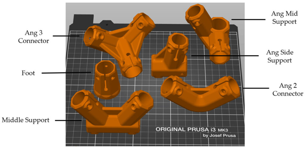
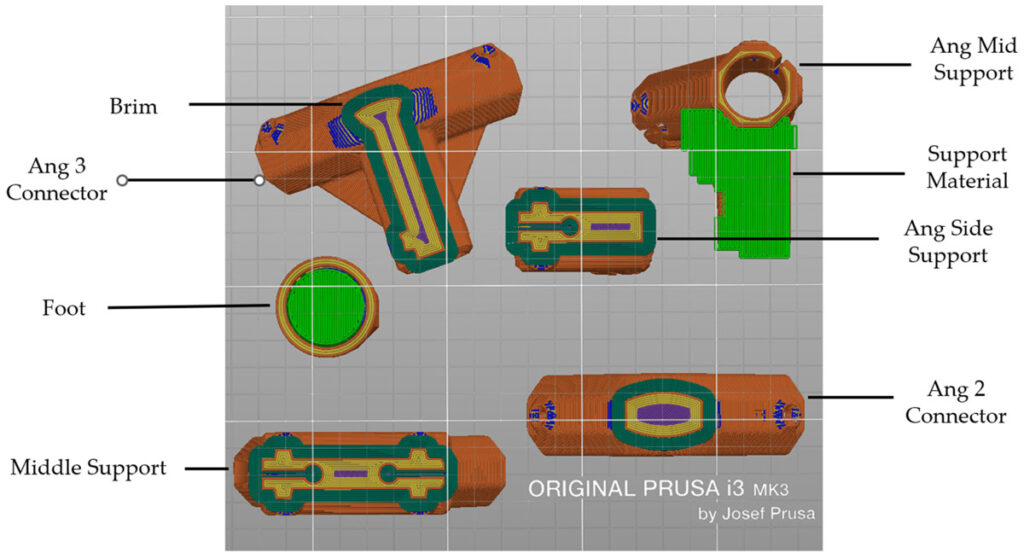
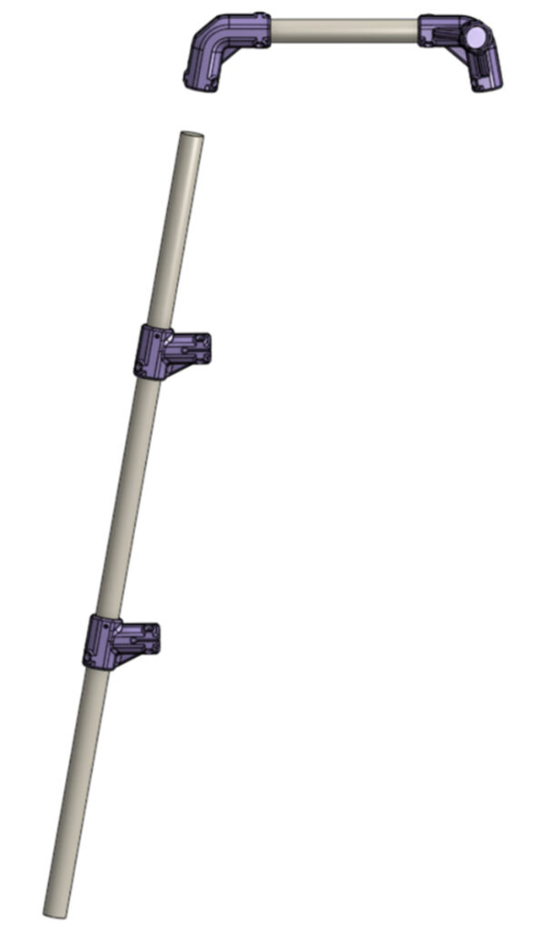
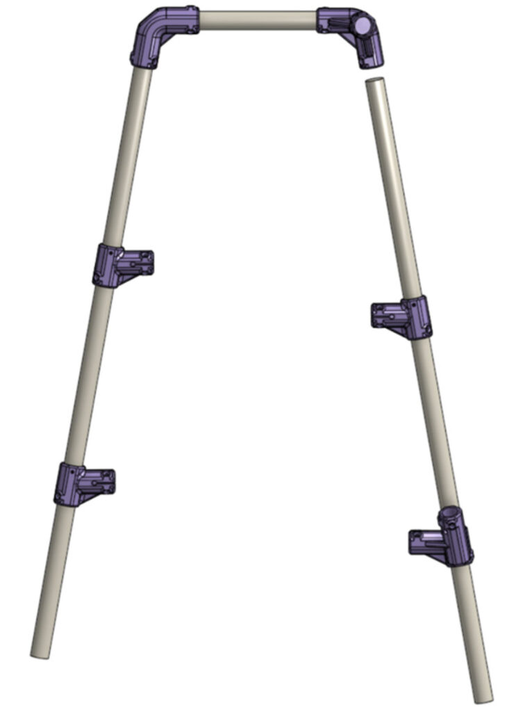
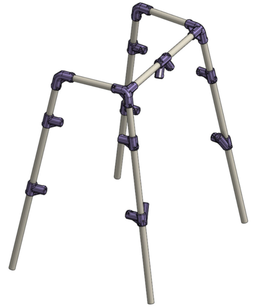
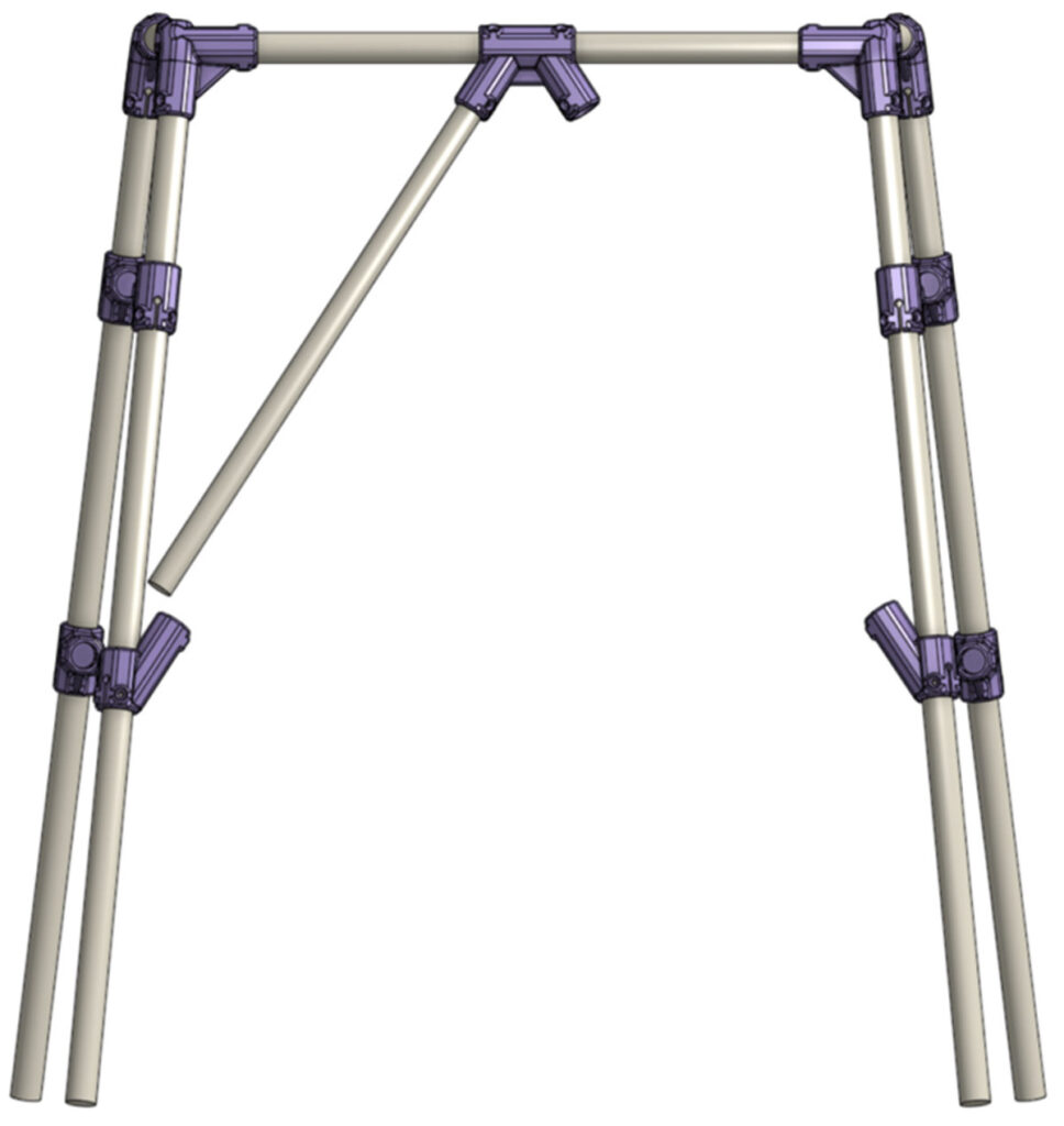
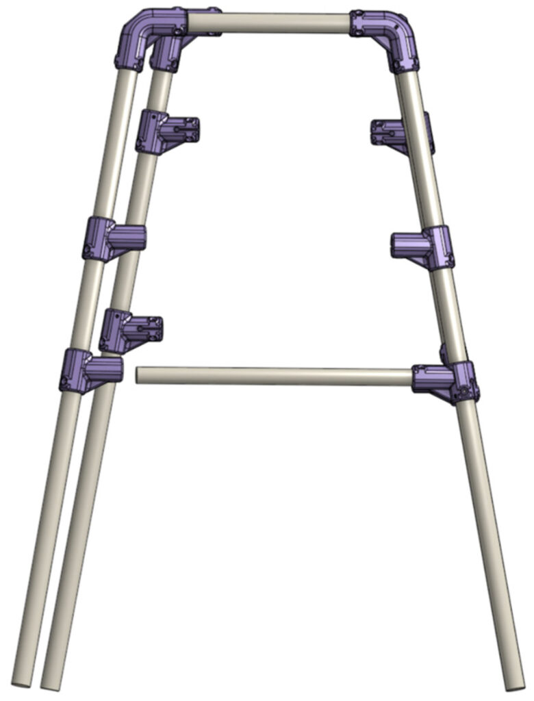
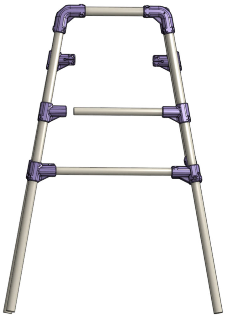
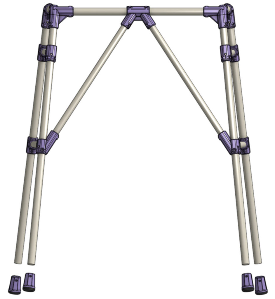
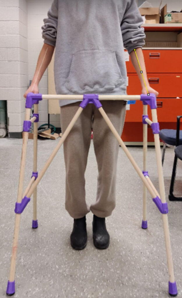
This walker’s stability and rigidity are achieved by three main features: an A-frame design, triangular bracing that angles inward from the front legs and meets centrally on the top bar, and two horizontal braces on each side (Figure A). The wooden dowel frame parts are connected by tough PETG plastic connectors.

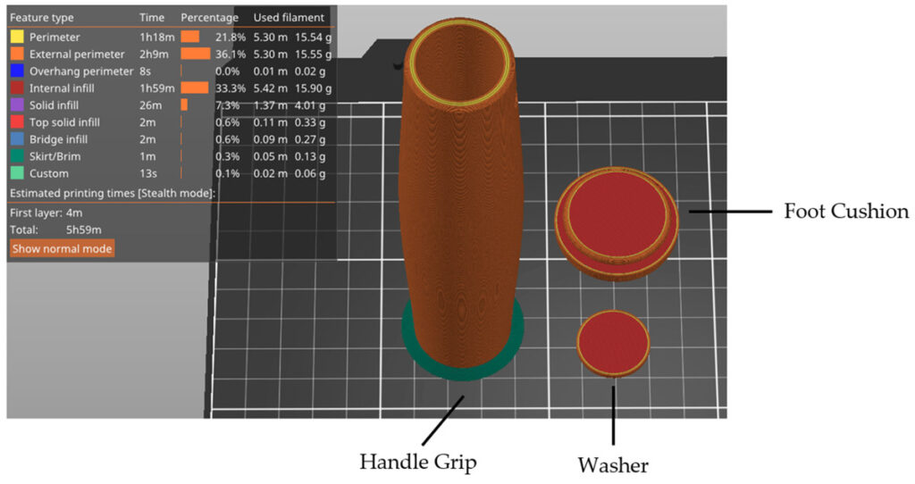
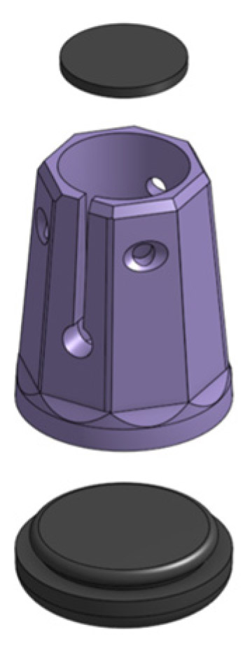
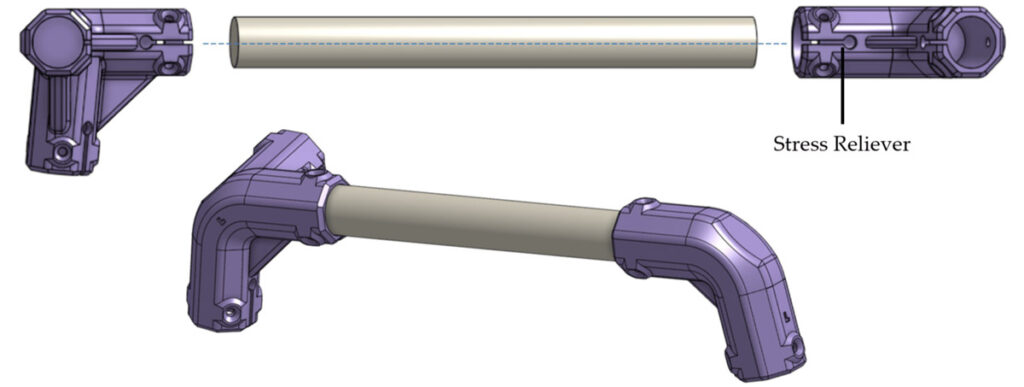
The three-piece foot design connects a rubbery TPU base to the dowels via a press-fit PETG body and #6 flat-head screws. These dual-material feet provide greater friction to improve the walker’s stability on smooth surfaces such as tiled floors. Similarly, a convex cylindrical TPU handle can be press-fit on the walker’s top sides to improve grip and comfort.

Figure B. Testing a distributed load that replicates the span of hands on the walker, by crushing it in a giant press.

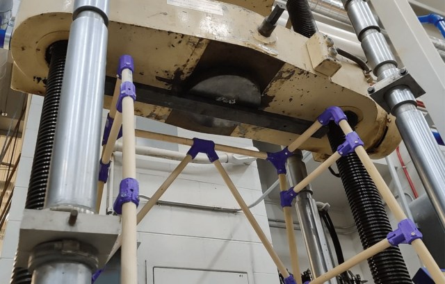
To ensure these walkers could safely withstand regular use, the team rigorously tested them to exceed the “static strength of walking frame” described in ISO 11199-1:2021, a standard that requires walkers to bear a purely vertical load of 1,500N — about 337lbs or 153kg — without cracking or breaking for a duration of 2 to 5 seconds. To study failure modes and locations, we exceeded this standard by testing the walkers to failure in a hydraulic press (Figure B).

Lateral loading was also considered. Initially, we played an energetic game of tug-of-war; controlled studies with a second hydraulic pump followed. You can read testing details and data here. Western did all the necessary testing for this design; you won’t need to replicate it as long as you follow the manufacturing instructions.

These walkers are designed to be customized. Not only do you size it for a specific person, but you should also choose the user’s favorite filament color!

We’re honored that our low-cost walker is included in the Project Library at Open Source Medical Supplies, whose Victoria Jaqua and Christina Cole helped prepare this article for Make:.

Project Steps

1. Print the Parts

Download the STL files from our page at Open Science Framework then print the parts. Use NinjaFlex TPU filament for the foot cushion, washer, and handle grip, and PETG for the rest. We used an open-source RepRap-class 3D printer, but many options exist (e.g., Prusa i3, Lulzbot Taz, etc.). Table 1 lists the names and quantities of the 3D-printed parts, and Table 2 provides the slicing parameters for the PETG and TPU components.

Figure C. Orientation of the 3D-printed parts on the print bed.
Figure D. 3D-printed parts (orange) with support locations (light green) and brim (dark green).

Due to the intricate shapes of the parts, each was oriented strategically on the print bed to avoid aligning the print layers with the anticipated fracture failure planes (Figure C). A brim of 0.5mm is recommended for parts with minimal surface contact with the bed. Support is required for both the Angled Mid Supports and the Foot Body components due to extreme overhangs; see Figure D for parts with support locations and brim. Finally, the handle was printed in a vertical orientation (Figure E).

Figure E. Printing orientation of handle, foot cushion, and washer.

2. Measure for the User and Cut the Wood

To ensure the walker properly fits the user, you’ll take measurements and adjust them with the calculation procedures detailed below. The quantity of each dowel part is specified in Table 3.

2a. Height of walker: Measure from the ground to the crease of the user’s wrist while in an upright position with arms relaxed on the sides and wearing shoes.

2b. Length of Leg dowels: Take the height of the walker established above and divide by cos(10°). Subtract 15mm for the thickness of the foot cushion and 30.75mm for the top 3-dowel joint. The final value is the length to cut four wood dowels for the legs.

2c. Width of walker: Walkers are typically 635–735mm wide, but can be as narrow as 560–610mm if the user requires it to fit through narrow entryways. For a comfortable fit, make the walker slightly wider than shoulder width, or more if the user has a wider stride.

2d. Length of Top Front dowel: Subtract 35.5mm from the width value established above.

2e. Depth of walker: Proper depth allows the user’s hands to fit comfortably within the handle. Ensure the handle is longer than the width of the user’s fist, with extra room determined by the preference of the user.

2f. Length of Handlebar dowel: Add 82mm to the length of the desired handle.

2g. Length of Angled Front dowel: Perform the sine law by dividing the calculated length of the Top Front dowel by 2, subtracting 12mm, multiplying by sin(95.296°), and then dividing by sin(27.404°). Finally, subtract 75mm.

2h. Length of Side dowels: These are the last dowels cut, as dimensions depend on the slight variations during construction. Once the Ang Side connectors are placed in their proper locations, measure from one end of the circular stress reliever to the other, and then add 9mm to that value.

3. Assemble the Feet

Figure F

Insert the Foot Washer flush into the top of the Foot Body (Figure F). It should fit snugly.

Slide the Foot Cushion into the bottom of the Foot Body and exert a good amount of force to press it into the tight space.

Repeat for each foot.

Tip: Press with your palm, which allows your full arm to exert force.

4. Assemble the Walker

4a. Measure and mark the center of the Top Front dowel. Then, mark half the length of the
Middle Support part on either side of the first mark.

4b. Align the Middle Support through the dowel with the marks and secure it using wood screws and a drill/driver. You’ll secure most, but not all, of the parts in this way as you go along.

4c. Measure and draw a center line along the length of the handlebar dowel (lateral area).

Figure G

4d. Secure the Ang 2 Connector [L] and Ang 3 Connector [L] onto each end of the handlebar, with both stress relievers centered on the line and the letters right-side up (Figure G).

4e. Secure a Leg dowel onto Ang 2 Connector [L].

Figure H

4f. Slide two Ang Side Supports [O] onto the Leg dowel with the stress relievers pointing to the right and the [O] symbol positioned at the top (Figure H).

4g. Secure a second Leg dowel onto Ang 3 Connector [L] on the end with the stress reliever pointing in the same direction.

Figure I

4h. Slide one Ang Side Support [□] onto the Leg dowel with the stress relievers pointing to the right and the [□] symbol positioned at the top. Following that by sliding the Ang Mid Support [L] (Figure I).

Figure J

4i. Repeat steps 4c–4h for the right side, and where you used the [O] part you’ll now use the [□] part. Insert (but do not secure) the last connection of the Ang 3 Connectors onto each end of the Top Front dowel. Now the overall frame of the walker is constructed (Figure J).

4j. Secure both Angled Front dowels into the Middle Support and lay the walker upside-down on a flat surface so the Top Front dowel side rests on the ground.

Figure K

4k. Slide one of the Ang Mid Support onto the other end of the Angled Front Dowel. Be cautious when doing so, as the fit will be tight, and ensure the dowel sits fully into the connectors (Figure K). Secure it once it’s in place.

4l. Repeat step 4k for the remaining side.

4m. Secure the Ang 3 Connectors onto the Top Front dowel.

4n. Position the walker right-side up. Secure the Bottom Side Support dowel into the fixed Ang Mid Support part.

Figure L

4o. Unsecure the Ang 2 Connector to add room and slowly move the corresponding Ang Side Support into the dowel (Figure L). Be cautious, as forcing it in place risks breaking the parts. Once fully in place, all the parts on that one side can be secured.

Figure M

4p. Move the top Ang Side Connectors down from the top by 150mm. Insert the Top Side Support into one of the connectors (Figure M). Try to align both connectors in parallel and slowly move them toward the top of the walker so the Top Side dowel starts to fit into the other connector. Keep moving them incrementally until the dowel is fully in. Secure with screws.

4q. Repeat steps 4o–4p for the other side.

Figure N

4r. Secure all four feet onto the ends of the Leg dowels (Figure N).

4s. Go walking!

Conclusion

Mobile Unlocked

This open source mobility walker has several user advantages:

  • Comfort and safety: The inward angles of the front triangular bracing structure won’t obstruct the legs of a sitting user; the A-frame creates rigidity by angling the front and back legs of the walker at 10° forward and backward, respectively, and angling the sides outward at 5°.
  • Weight: The device mass was cut by about 20% (0.5kg or 1lb) compared to commercial walkers. Any difference in weight is significant for users with diminished strength, as static walkers require repetitive lifting when the user is in motion.
  • Strength: All testing baselines demonstrate that the walker is robust — the user-applied load limit was found to be 375.3kg (827lbs) for vertical failure and 197.8kg (436lbs) for horizontal failure.
  • Affordability: Finally, this open-source walker costs between $48–$68, which aligns with the least expensive commercial walkers or used walkers at a thrift store.

The cost could be brought down even further by substituting waste plastic for commercial 3D printing filament, and by using alternate structural wood components — possibly reducing costs to less than 10% of the current.

More derivatives are also possible. When I had a broken foot, I used a single walker leg as a cane until it healed. Our lab at Western University is now testing a derivative of this design to make low-cost crutches!

Learn More

This article appeared in Make: Volume 88.