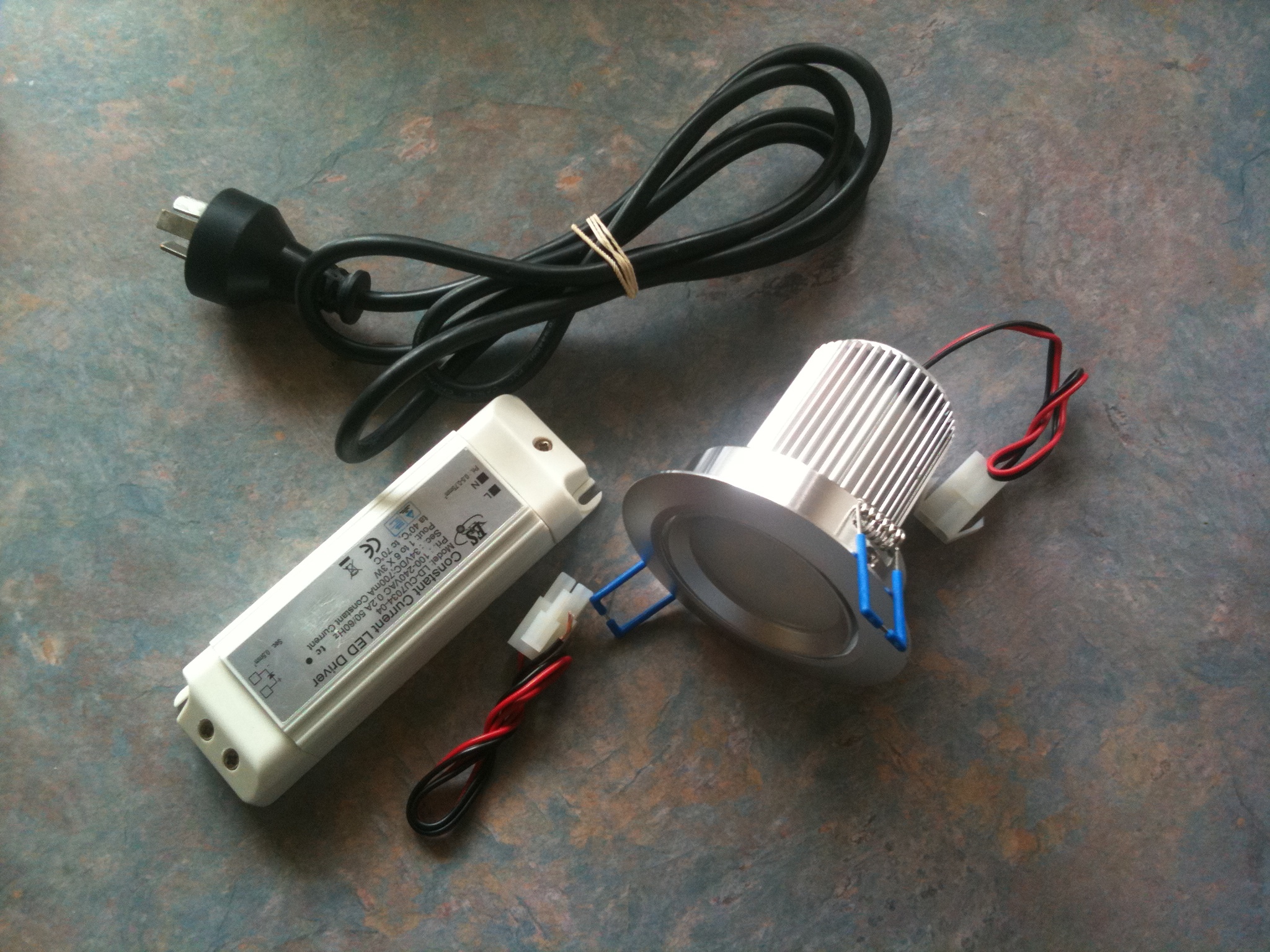
Price AUD $32.95 Complete kit.

Shipping cost is extra.

Discount on bulk (email us).

NOTE: LED Driver is not included in kit (extra)

I have a range of new LED lighting kits and parts available. I have designed street lights / down lights / pool lights / commercial lighting kits as well.

Keep a lookout as I will be bringing out more LED lighting kits from my design range. Now you can build up your own LED lights, and if you what to learn about LEDs then my new LED kits should do the job! They are ideal for schools and clubs or someone who just wants to change to LED lighting in their home or business.

Whatever the case may be I am available any time to help out, so if you need a kit or LED parts then let me know by email (eyecatchu@yahoo.com.au) or by Mob: 0408458645.

Project Steps

Check List

Check kit parts list. 1 x Heat sink casing / 1 x PCB 1 x LED Lens cover / 1 x 13 Watt LED 1 x wire lead

PCB Plate.

Now check the two screws on the PCB top plate. Tighten them if they are loose.

NOTE: Don’t over-tighten them, or you will strip the threads.

Mix Paste

Mix a small amount of thermal epoxy paste for a few seconds. Mix well.

WARNING: BE CAREFUL NOT TO GET IT ON YOUR HANDS!

Apply Paste

Once it is mixed, put some over the two screws on the PCB top plate and also on the bottom of the LED PCB. Then place the LED onto the top plate. Press down gently on the sides of the LED only. Now leave the epoxy to cure.

NOTE: Make sure the PCB hole is in the centre of the heat-sink.

WARNING: DO NOT TOUCH THE LED SILCON LENS (YELLOW PART)!

NOTE: Be careful not to get the epoxy paste on your hands.

Mount LED

Put some paste on the bottom of the LED, then stick it down onto the top of the heat-sink. NOTE: Make sure the LED “+ve” and “0v” solder pads are centered with the U groove that’s on the heat-sink side.

WARNING: LEDs ARE STATIC-SENSITIVE, SO YOU MUST WEAR AN ANTI-STATIC WRISTBAND WHICH IS CONNECTED TO EARTH.

Attach Power Leads

When the paste has cured, solder on the power leads. I used small pliers to hold each wire.

The finished PCB with power leads and LED.

Sleeving

Now place the small white sleeve over the wire leads and slide it up to the top of the LED.

Hold down the wire lead making sure that the white sleeve is pressed firmly in the heat-sink U groove.

Lens Cover

Now glue the lens cover inside the top casing. Note: Be careful not to get glue on the lens cover.

Press gently in the centre of the lens cover for a few seconds to make sure that it is firmly seated.

NOTE: Be careful not to get glue on the lens cover.

Attach Top Casing

Next, screw the LED lens holder in place (not too tight).

Power Supply

DC Power supply set for testing lamp. Voltage is set between 15-21VDC. Current is set at 200-250mA.

WARNING: Maximum current for this lamp is 700-1030mA.

LED Lamp Complete

If you have reached this stage, then congratulations! You are just about finish this project; all you need to do now is power it up. Connect the lamp to a DC power supply with voltage set at 15-18 VDC and current set at 350-700mA for testing.

WARNING: These LEDs are super-bright, so make sure the lamp is pointing at a wall! DON’T LOOK AT THEM HEAD-ON WHEN THE POWER IS ON!

NOTE: This lamp needs a constant-current LED driver between 700-1030mA with voltage between 18-21 VDC. An LED driver for this lamp is available from James Electronics.

Finished Project

Congratulations on assembling your new LED Ceiling Down Light!