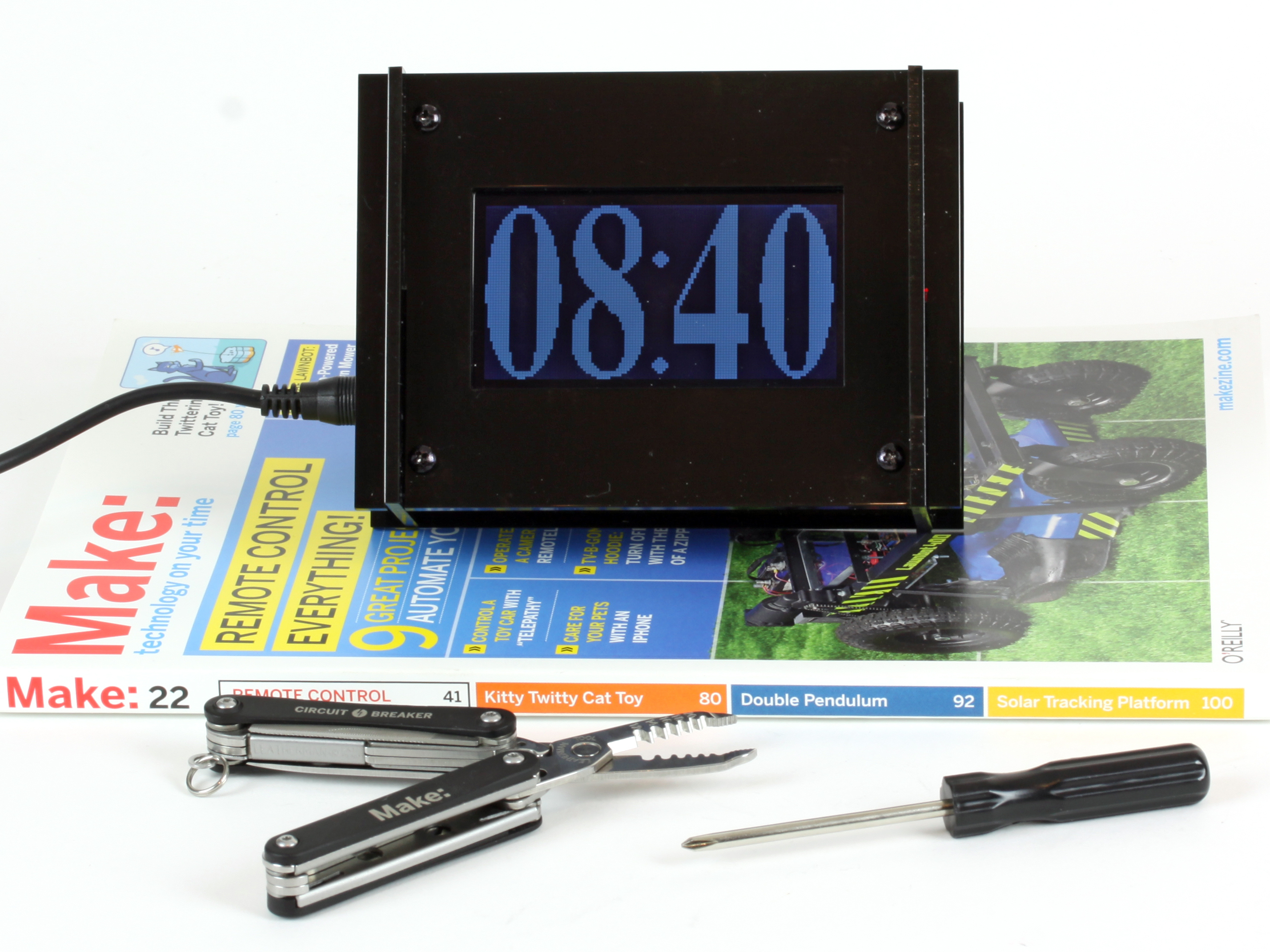
You’ll need some basic soldering & hand tools to assemble the Monochron. The good news is that this is a pretty basic kit and even if it’s your first soldering project, it shouldn’t take more than 2 or 3 hours to put together.

Buy the kit at the Maker Shed.

Project Steps

Check the parts against the BOM (bill of materials).

Get ready to solder!

Add all the resistors. I found it easy to add all of them at once. Just bend the leads and insert them into the PCB. Once inserted, bend them outwards to hold them in place.

Add one 1Kohm resistor (Brown Black Red Gold) to the spot labeled R1.

Add all the other 1Kohm resistors (Brown Black Red Gold), 5 in total, to the spots labeled R3,R4,R5,R6 & R7.

Add the two 2.2K (red red red gold) resistors to R8 & R9.

Add one 100-ohm resistor (brown black brown gold) to R2′ (<- notice the '). Do not use R2 (no ') unless you want a fixed brightness on the LCD; something you most likely do not want!

Adding the capacitors

Add the ceramic capacitors to C1, C3 & C5. They are not polarized, so you can insert them either way.

Flip, solder & trim!

Building the power supply

Add the DC power jack.

Make sure you use enough solder. This is an electrical and mechanical connection

Next add a 1N4001 protection diode to D1. Diodes only conduct electricity in one direction, so its important to orient it correctly.

The white stripe at one end is the cathode. On the PCB there is a silk-screened diode and it has a matching white stripe. Make sure to match the silkscreen stipe of the diode to the stripe on the actual diode.

Add the 7805 voltage regulator to the area labeled IC2. Orient the regulator to the silk-screened outline on the PCB.

Flip, solder & trim!

Test the power supply.

Clear your table of everything (we don’t want to short anything out). Plug in the power supply, and break out your multimeter.

Measure the voltage between the negative side of the power jack and the (+) spot on the PCB labeled C4. Zoom in on the image to see exactly where to measure.

You should get a voltage of ~ 5.0v (+/- .1V is OK).

Next we will solder in the two electrolytic capacitors.

C2 is the 47uF/25V electrolytic capacitor. Electrolytic capacitors are polarized. They need to be oriented properly. The capacitor has one leg that is longer than the other leg. This longer leg is the positive (+) lead. Make sure to place the capacitor into the spot labeled C2 and the long leg goes into the hole labeled “+”. Double check!

Once you insert the leads in the proper spots, bend the capacitor to lay flat behind the power jack. (See picture.)

C4 is a 100uF/6.3V electrolytic capacitor. This needs to be oriented the same as the other capacitor. Make sure the long lead goes in the hole labeled “+” at C4. Again, double check!! No need to lay this one flat.

Add the IC socket.

The socket has a “notch” at one end. Make sure that this “notch” matches the notch on the silk-screen.

The legs of the socket arent long enough to bend and hold it in place…..

Tip alert!

To solder the socket in place: Wrap some solder around whatever you can as pictured.

Hold the socket in place with your hand.

Flip it over and solder it in place as pictured. Make sure to solder every pin!

Alternatively , you could use some tape to hold it, but this is how I do it.

Insert piezo speaker into the area labeled SPK

It isn’t polarized, so either way is fine.

Flip, solder, and trim!

Time to test!

Insert the IC.

Make sure to orient it properly. The notch should match the notch on the socket (which should match the silk-screened notch on the PCB).

You may have to bend the legs of the IC so they are straight. Sometimes they are flared a bit. Mine were straight enough to insert them into the socket.

You can straighten them by gently rocking the IC (on its side) on a hard, flat, surface.

Now go ahead and clear the work area again, and plug the board in. You should here beeping.

Beep! Beep! Beep! Yea! If not, unplug immediately and go back and check everything! Did you get 5V in step 5? Is the IC in correctly?

Next add the red LED to the area labeled LED1.

LEDs are polarized. The long lead goes into the hole labeled “+”.

Make sure to leave enough of the leads to bend the LED over as pictured. It should extend past the PCB by about 1mm.

Flip, solder, and trim!

Now add the switch to SW1.

Use the same technique as the socket to solder this in place.

Clear your work area, plug the PCB in, and give it a test.

The LED should light up depending on the switch’s position. Flip it on and off to test.

Adding the real-time clock parts. (RTC)

These components keep very accurate time with just a coin cell battery.

First add a “blob” of solder to the pad labeled BAT.

Next, solder in the battery holder. Make sure it is oriented the same as the silkscreen.

Now add the 32.768 KHz watch crystal (small metal tube) Q1. Lay it flat prior to soldering (as pictured).

While you are at it, go ahead and solder in the 8-pin socket for IC3. (Make sure to align the notch as it is silk-screened on the PCB.)

Now let’s add the three buttons to the PCB in the areas labeled S1, S2, S3.

Make sure to use enough solder!

Add the trim pot to TM1.

Now it’s time to add the LCD.

Start by trimming a matching amount of male header pins the length of the supplied female headers.

It’s easiest to insert the male header pins and trim them in place.

Next, solder in the female header pins into the PCB.

Make sure they are laying flat prior to soldering.

Solder all the pins using the same technique as step 7, or use some tape to hold it in place.

Next, insert the DS1307 RTC IC into the matching socket. Make sure to align the notch of the IC to the notch in the socket.

Insert the male header pins into the female header (long pins go in the socket).

Add the LCD to the male header pins.

This gets a bit tricky!

Hold the LCD and solder at least 1 pin on each side.

Now you can stuff something under the LCD to help keep it parallel to the PCB and solder the rest of the pins on the LCD.

Insert the battery, positive (+) side up!

Clear your workspace.

Power it up!

Adjust the contrast with the trim pot that is directly below the switch and red LED.

You should see the time! Yea!

Time to make the included enclosure.

Start by removing the plastic from all the acrylic pieces.

Now temporarily screw the aluminum spacers between the boards from the back.

Place the left and right sides on the clock “guts.”

Now slip the front cover on. Easy!

I’m not a big fan of the chrome screws. No worries; a little permanent marker and I think they look great!

Now screw on the front faceplate.

Be sure to add the nylon spacers behind the faceplate and in front of the circuit board.

Use a pair of pliers to hold the spacers.

Now you can remove the screws that were used to temporarily hold the aluminum spacers in place. (See step 20.)

Add the top and bottom pieces of acrylic.

Notice that the top piece has a little “bump”. This bump, or key, needs to face the back of the clock.

Note: In the picture the clock is upside-down.

Now you can slide on the back cover and screw it in place.

I colored these screws black too. I think it looks great!

You’re done!