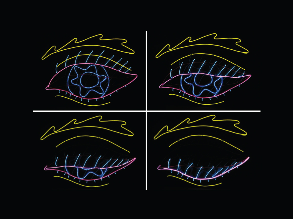
Here’s a project that illustrates the steps and considerations for using lightwire to create a successful animated image: in this case, a large, blinking eye.

To get well-versed on EL wire, read the wiki page.

Project Steps

Sketch your idea

First, sketch out the object you want to animate. We’ve seen running horses, jumping kangaroos, flying saucers, and leaping dolphins. The best designs can be understood from just a few contours.

Make a full-sized drawing

Once you’ve refined your idea, draw it at full size on one or more sheets of paper. You need to figure out which elements are always on — the common frame — and which will be animation frames.

In our case, the common frame included the eyebrow, the folds above and below the eye, and the eye’s bottom edge and eyelashes. The animation consisted of 4 frames that showed the eyelid and lashes, iris, and pupil in various stages of open- and closed-ness. To distinguish the various parts and make the animation easier to view, we decided to use yellow for the eyebrow and folds, green for the lashes, pink for the eyelid, and blue for the iris and pupil.

Transfer the drawing to the mounting medium.

We made a full-sized master drawing of the fully opened eye (the common frame plus frame 1) and then 3 more drawings for frames 2–4. To make the movement of the upper lashes appear smoother, we drew them on a separate piece of tracing paper and simply translated them downward for frames 2–4 without foreshortening the lashes’ length. This allows successive lash segments to overlap from frame to frame, which helps the viewer follow them and see them as the same thing. The animated movement reads better this way, even though real lashes don’t stay upright.

You can attach lightwire to almost anything. We mounted our eye to a sheet of foamcore board. To transfer the drawings, we taped them onto the board, then followed along each line with a stylus, making an indentation by pushing down into the board.

Then we filled in the indented lines with different colored pencils for each frame.

Measure and cut the lightwire.

For each eye image segment, hold the corresponding color of lightwire along its line to measure out the proper length, then cut it to size, adding about 6″ of extra length. Label each segment with tape to identify it, for example, “eyelash/frame 1.” Group the cut segments together by frame: common or 1–4.

For elements like the eyelashes, which are laced in and out of the board, follow the wire’s path back and forth with a piece of string, holding it along the way with bits of masking tape. Then measure the lightwire against the string and cut it to length plus 6″.

Lightwire can’t be folded or bent too tightly. For corners, use separate segments or thread a single segment out the back, loop it, and bring it back to the front at a new angle through an adjacent hole. To black out short sections, cover the wire with tape or heat-shrink.

Attach the leads – Outer vinyl sheath(s)

Before mounting, each segment needs to be connected to its 2 lead wires. Our leads came from cutting open a network cable, which contains matched pairs of wires in 4 colors. This is helpful for color-coding our 4 animation frames. (Five colors would be even better, to include the common frame.) Here’s how to connect each segment to its leads:

Strip off about ¾” of the lightwire’s outer vinyl sheath(s) at one end.

Attach the leads – Tease, bend and solder wires

Tease away the tiny wrap wires, then stick a cuff of copper tape around the sheath, right behind where you began stripping.

Bend the wrap wires back over the copper tape and solder them to the copper tape.

Attach the leads – Core conductor wire

Scrape off the phosphor layer to completely expose about 3/8” of the tip of the core conductor wire.

Cut and strip 2 leads about 12″ long. Solder one to the bare core conductor and the other to the copper tape. Use the proper color leads to designate the frame (but stripe vs. solid can go either way).

Test the segment by connecting it to a working driver. If it lights up, cover the joint with a piece of heat-shrink tubing.

Mount the segments, frame by frame.

Starting with the common frame, attach all the segments for each frame to the front of the board, following the drawing and running the leads out the back. To minimize the spaghetti in back, pick one side of the board to carry the leads, and drill pilot holes on that side where each segment starts.

To hold the segments down and guide them around curves, we made “staples” out of 28-gauge steel wire. Drill pilot holes where you want the staples to sit, run each end of the staple through the holes, then fit the staple snugly around the lightwire and fold its ends flat on the backside using needlenose pliers.

The blinking eyelid covers different amounts of the blue iris and pupil, so frames A–C all include iris and pupil segments, even though these elements don’t move. Where the frames’ segments represent the same lines in the original drawing, we mounted them side by side so they wouldn’t block each other.

Bundle the leads.

After mounting all the segments for each frame, bundle the leads together in back and label them for final connection later.

Connect the frames to the driver and sequencer.

Test each lightwire strand again by alligator-clipping its leads to a driver. Although we tested them before, the soldered connections can break when the strands are mounted, and it’s easier to identify and repair individual elements before they’re connected together.

The 10-channel sequencer can switch from frame 1 to frame 4, but it doesn’t include an always-on output, so we connect the common frame leads to a different box, a cube driver.

For the wires in each frame, bundle all of their leads together and separate the solid and striped wire pairs. Twist the solid leads and the striped leads together into 2 pigtail connections for each frame, then solder the 2 masses to a snap connector. You should wind up with 5 snap connector plugs, each of which connects in parallel across all the segments in a single frame and plugs into the sequencer or cube driver.

Final assembly.

The sequencer and driver both run off the same 12V battery brick. Each has a battery snap that plugs into the brick’s 9V-style terminals, so you need to solder an additional 9V battery snap to connect it to both boxes. Then mount the brick, sequencer, and driver together on the back of the board near the lead bundles. We just stuck them on with cardboard, metal fasteners, and zip ties, and then neatened up the wires in back with more zip ties.

Finally, plug the frame 1 connector into the sequencer’s channel 1 port, frame 2 to channel 2, 3 to 3, and 4 to 4. Plug the common frame connector into the cube driver. Choose the sequencer pattern that makes sense for the project; in this case, “1-2-3-4-3-2-1” gives the illusion of the eye opening and closing. You’re done!

Conclusion

This project first appeared in MAKE Volume 21, page 142.