Photo by Hep Svadja
Read articles from the magazine right here on Make:. Don’t have a subscription yet? Get one today.

Never be without a worthy adversary with the Air Hockey Robot EVO. It’s easy to set up and deploy, and it’s controlled by your Android smartphone.

This open source robot can be scratch-built using readily available components and 3D-printed parts, or you can buy it as a kit. It requires an air hockey table — we have one we recommend that fits our bot, but you can modify the dimensions to accommodate others.

It’s a fun project that teaches science, robotics, computing, visual recognition, and engineering.

How it Works

The smartphone is the robot’s brain. Running the Air Hockey Robot app, it processes the data captured by its camera in real time, detecting features on the playing court and making attack/defend decisions according to the detected objects’ locations and their trajectories (Figure A). Your own device can defeat you in a real game!

Figure A. Step shots courtesy of JJ Robots

Uniform illumination is extremely important for the vision system to work, so avoid shadows, reflections, and if you can, fluorescent lighting.

Modifiable and Portable

It’s easy to adjust the skill level of the robot, to play with children, for example — just go to the app configuration menu and set the difficulty. You can also set it to “manual” mode and control the robot using your finger, and there is a PlayStation 3 Camera version for the robotics enthusiast, which runs on a regular PC and allows you to modify the vision system. The robot is easily removed from the table for transport, or when you’d rather play against another human.

How it’s Made

Figure B

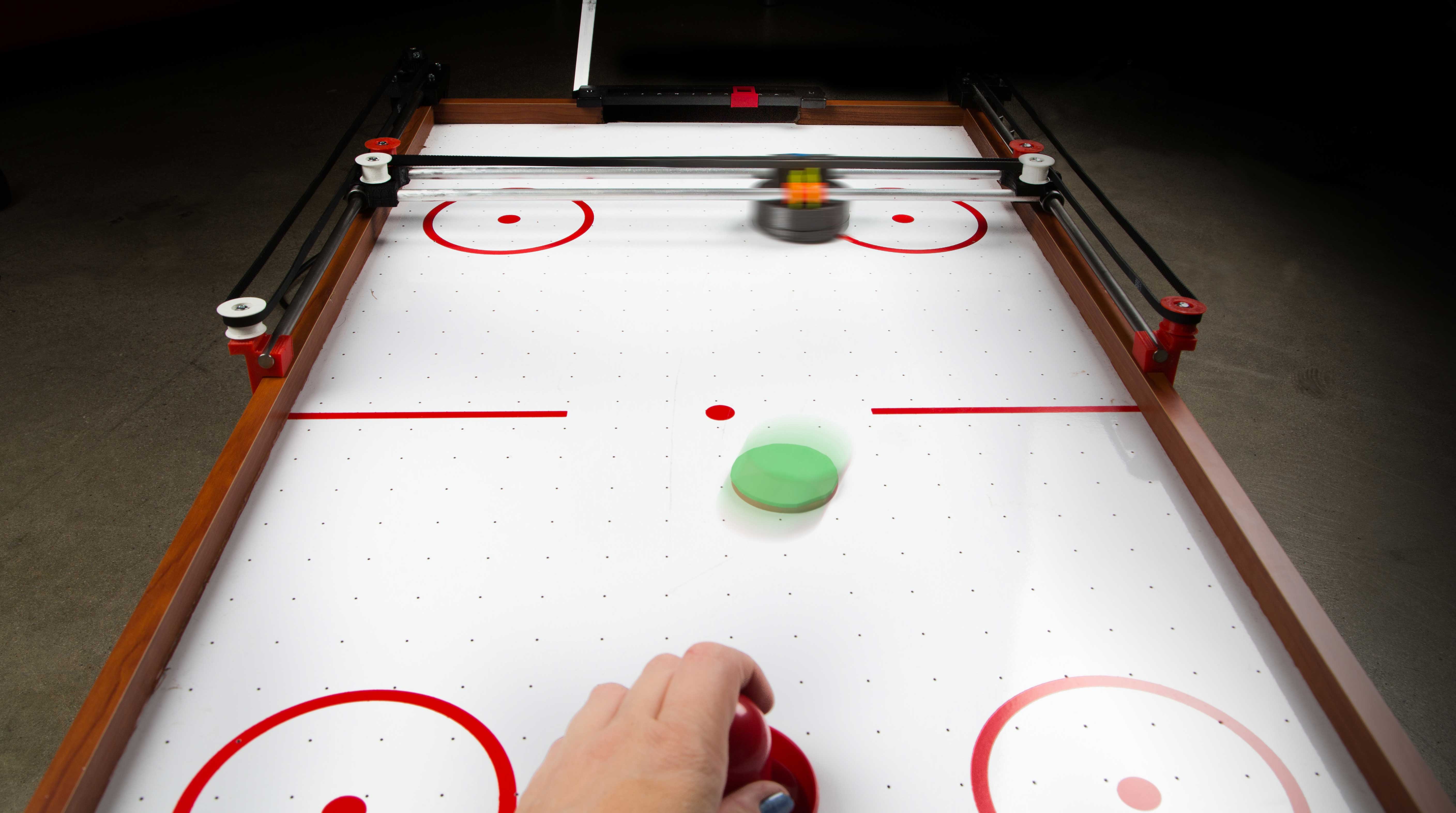
The robot is constructed from metal bars, a timing belt, and 3D-printed parts. The electronics consist of the JJRobots Brain Shield, an Arduino Leonardo, 2 stepper motor drivers, and a 12V fan to cool them (Figure B). The robot is locally controlled by the Brain Shield, which dictates its speed and acceleration, sending the appropriate pulses to the stepper motors. For complete instructions visit jjrobots.com/air-hockey-robot-evo.

Figure C

The key to a flawless working robot is the H-bot system (Figure C); this structure allows the robot to move to any location on its playing field using only two motors (Figure D). The H-bot needs to run smooth and be strong at the same time. The better you set it up, the greater the accelerations you can reach. Here’s how the robot mechanism goes together.

Figure D

Project Steps

1. ATTACH MOTOR AND ASSEMBLE PULLEYS

Figure E

Affix the motor to the motor supports with M3×6mm bolts, 3 per motor (Figure E). Then mount 2 of the 623 ball bearings inside each of the 6 pulleys (Figure F) with an M3×25mm bolt. Secure the fan to its support using 4 of the M3×15mm bolts and M3 nuts.

Figure F

2. ASSEMBLE THE X-AXIS

Figure G

Take the 2 aluminum pipes and insert both into a lateral slider cap. This is the most important part of this assembly. It can seem quite hard to insert the pipes into the 3D-printed parts, but the sturdiness of the structure will depend on how tight everything is. Twisting the pipes as you’re pushing them helps. If necessary, use a hammer (gently) to prod the pipes into the channel. Insert the bushings, shown in red in Figure G, then place the second lateral slider cap on the other end.

Figure H

Screw on four of the assembled pulleys — no need to use a nut (Figure H). Attach the paddle (aka the goalie, striker, or mallet) in place with 4 zip ties, running them through the two channels on either side of the paddle, and tightening them so as to just hug the plastic bushings. Trim the excess zip ties (Figure I). Test that the paddle slides easily along the pipes. If it doesn’t, olive oil will greatly reduce the friction between the aluminum and PLA plastic. Attach the base of the paddle using four M3×15mm bolts. This is the robot’s X-axis.

Figure I

3. BUILD THE SIDE RAILS

Figure J

Attach a motor pulley to each motor’s axis with four M3×10mm bolts and nuts, tightly — these pulleys will transmit all the movement to the robot (Figure J). Affix each of the remaining two pulleys to a side support using a self-locking nut (Figure K). Insert one end of the steel bars into each. Slide the LM88UU linear bearings onto the bars, then insert each into a motor support (Figure L). This completes the H-bot build.

Figure K
Figure L

Caution: Always, always keep the fan blowing while the Air Hockey Robot is working. The stepper motor drivers might get damaged if there is not a constant airflow cooling them down.

Another word of Caution: Sudden accelerations of the robot within its playing area could catch you unaware. Before adjusting anything remember to disconnect its power supply

4. Attach to the Table

Figure M

At one end of the table, loosen the top screw on the side. Set the motor support in place on top of it, then screw it back in. Use a wood screw to fix it in place (Figure M). Repeat on the opposite side.

Figure N

Attach the side supports on either side of the table using two wood screws (Figure N). Gently snap the robot’s X-axis structure with the sliding pusher onto the LM88UU bearings on the steel bars. The X-axis structure should easily slide up and down the side steel bars. If you find any burr inside the channel where the linear bearing is, remove it gently. Both LM88UUs have to be perfectly aligned in order to avoid any kind of friction with the steel.

Check out our complete instructions on our website.

Going Further

Mount two robots per table, one on each side, and have them compete, or compare different gaming strategies in a tournament. Remember, you can easily change their behavior via the Arduino code. Game on!