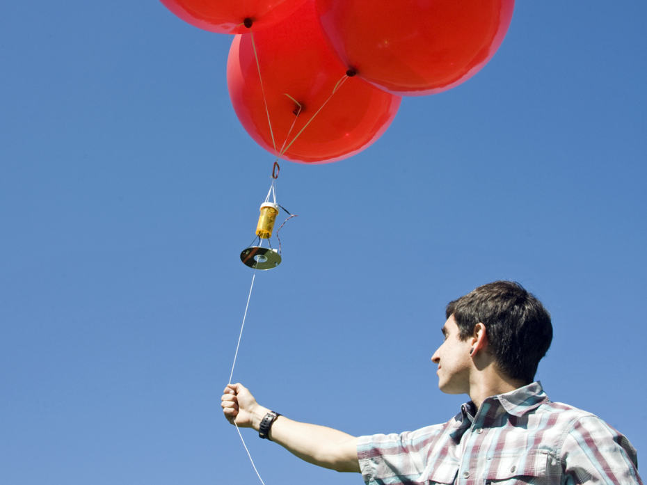
Baloon Imaging

The first time I saw a satellite photo of my house on Google Earth, I expressed shock at the “Big Brother” implications of an all-seeing, commercial eye-in-the-sky. But meanwhile, I was also secretly disappointed with the picture quality and clarity because (Orwellian angst aside) I needed better overhead images for my own use — to help me lay out a new driveway and complete a birds-eye-view CAD drawing of our lot. So I decided to design and fabricate a simple helium balloon “satellite” camera platform, tethered to the ground for ease of control and retrieval, and dedicated to a single purpose: to capture aerial images of my house and surroundings.

Here’s how I completed this project using inexpensive and readily available components — helium balloons on a nylon kite string, a drugstore camera perched on a platform made out of an old CD, and a PICAXE microcontroller housed in an empty pill bottle.

What will the next generation of Make: look like? We’re inviting you to shape the future by investing in Make:. By becoming an investor, you help decide what’s next. The future of Make: is in your hands. Learn More.

Project Steps

Make the trigger board.

For all connections, refer to the project schematic seen here (downloadable at http://www.makezine.com/24/ballooncam). To stabilize voltage regulator operation, I added an additional 22μF electrolytic capacitor across the power leads, in parallel with the Proto Kit’s included 100nF cap.

Assemble the PICAXE Proto Kit, soldering the following components at the locations indicated on the printed circuit board (PCB): 8-pin IC socket, stereo download socket, 3-pin header, 10kΩ resistor, 22kΩ resistor, and 100nF capacitor. These components are small, so a helping hand with magnifier or a tabletop vise will come in handy. Don’t connect the battery clip yet.

Once all parts are in place, carefully place the microprocessor chip in its socket, with pin 1 (indicated by the notch) pointing away from the prototyping area (or you can place it later; see Step 1e). Also, move the jumper on the 3-pin header to the PROG side to enable it for programming.

Thread the leads of the battery clip through the 2 holes in the Proto Board PCB, and solder the black wire into place on the bottom of the board.

Insert the voltage regulator through 3 holes near the center of the PCB. Run the red wire from the battery clip across the top of the PCB and connect it to the regulator’s input pin (indicated by a dot). Using a wire jumper, connect the middle (ground) pin of the regulator to the black wire from the battery clip. Use another wire jumper to connect the LM2940 output pin to the PCB, at the location marked “RED,” where the red wire from the battery clip would normally attach.

Insert the 22μF capacitor through the 2 PCB holes indicated by (+) and (–), and solder it in place. Be sure to watch polarity; the stripe on the cap goes on the (–) side.

Insert the relay into the PCB at the forward edge so that the single switch terminal dangles off the side of the board and the other 3 pins run through holes. The bottom left pin should run through the hole that’s 3 up from the bottom of the board and 2 from the left.

Insert the 1N4001 diode into the through-holes that connect to the relay coil terminals so that its body drapes over the top of the relay. This diode protects the PICAXE from back electromotive force when the relay is de-energized. Using jumper wires, connect one of the relay coil terminals to the PCB ground pin and the other to PICAXE output 2 (pin 5 on the chip).

Solder about 1′ of 18- to 20-gauge wire to each of the relay switch terminals. Use wire cutters to cut a 2-pin length from the male breakaway headers, and solder the 2 pins to the wires’ other ends.

Cover the solder joints with heat-shrink tubing or electrical tape to prevent shorts and to add strength.

Program the triggering.

Download and install Revolution Education’s free AXEpad software from http://www.rev-ed.co.uk/picaxe.

Download the BASIC file Camera_Timer.bas from http://www.makezine.com/24/ballooncam, then open it up in AXEpad. This simple, 14-line routine waits 20 seconds from the time of initial power-up to give time to replace the pill bottle cap, takes one picture to confirm that it’s running, waits another 20 seconds to let the balloon rise, then begins snapping pictures every 2 seconds. You can modify this to suit your needs.

To load this code into your Proto Board, connect the PICAXE programming cable between your computer and the board’s programming jack, then click the Program button in AXEpad, in the upper right.

Modify the camera.

The specifics of this step will depend on the camera you use, but it’s a simple mod, and readers with basic electronics skills should have no problem. The camera shown here is Shift3 brand and was purchased for $11 at a Rite Aid pharmacy.

Remove the stick-on label from the front of the camera (or the side, for the Aries camera) to reveal a screw that holds the case together.

Remove the screw with a small Phillips screwdriver.

Gently pry the camera shell open using a flathead screwdriver.

Remove the 2 screws holding down the circuit board, and also unscrew the keychain clip, which we don’t need (with the Aries camera, remove 3 screws to detach the board).

Turn the board over so that the lens is visible. Handling the board by the edges only, and without touching any parts, use tweezers to remove the black potting material from around the shutter switch, exposing solder terminals at its base.

Solder wire leads to the 2 newly exposed switch terminals.

To make room for the shutter switch wires to exit the case, use pliers to cut a hole in the plastic on the side opposite the lens (with the Aries camera, instead of cutting the case you can remove the pop-up viewfinder lens assembly and route the wires out of its hole.)

Replace the board and screw it back into the case, routing the shutter switch wires out, and reassemble the case.

Cut a pair of adjacent female connector headers, and solder one of the wires to each. This will connect to the male header pair from the trigger board.

Assemble the satellite structure.

Drill 4 equidistant 1″ holes around the bottom of a pill bottle large enough to hold the microcontroller board and battery (about 2″ in diameter and 4″ tall). Drill another hole through the center.

Insert 6″ lengths of stiff 12-gauge solid wire into the 4 perimeter holes and extend them downward from the bottom of the bottle. Inside the bottle, bend the tops of the wires so they stay in place when you pull the wires from below.

Mark and drill 4 uniformly spaced 1″ holes around the periphery of a spare CD or DVD.

Thread the 4 wire standoffs from the bottom of the pill bottle through the 4 holes on the CD, bend them to lay flat underneath the surface of the CD, and secure them in place with duct tape, or by twisting them up and around.

Grab the spool of kite string, and route the free end up through the center hole in the CD and through the center hole in the bottom of the pill bottle. Tie it off to the 12-gauge wires inside the bottle.

Attach the camera and balloons.

Mount the modified camera to the top surface of the CD with double-sided foam tape so that the lens of the camera looks down through the hole in the center of the CD.

Insert the PICAXE board and 9-volt battery into the pill bottle, but don’t connect the battery yet (powering up the board will start the program running).

Drill a ¼” hole in the center of the pill bottle cap and 4 more small holes around the periphery, uniformly spaced and as close to the outside diameter as possible.

Inflate the balloons with helium, tie each one off with a knot, and tie on a 1’–2′ piece of kite string. Tie the balloons together to form a tight group, and tie them all to the carabiner. When finished, you’ll have the balloon group attached to the cap of the pill bottle, and because the balloons attach to the satellite only through this cap, it must be of the childproof variety to make sure it stays on securely.

Finally, attach the bottle cap, routing the camera connector wire through the center hole. You’re ready to fly!

Use it.

Once the balloon-satellite is fully assembled you’re ready to launch. Here’s how:

1. Plug the headers together from the trigger board and the camera, and turn the camera on.

2. Unscrew the top of the pill bottle, being careful not to let it fly away. Inside the bottle, connect the 9-volt battery to the Proto Board battery cable, and quickly screw the top back on.

3. Let the satellite go — up, up, and away! If you look carefully at my photos, you can see the kite string along with a knot I had to tie due to some poor planning. I hope that readers can plan their string routing a little better than I did and keep the images knot-free.

Conclusion

This project first appeared in MAKE VOLUME 24, page 80.