Readyformycloseup

The Bass Bump Headphone Amp is an audio accessory you can build to improve all of your private music listening. It has enough power to give clear sound and punchy dynamics through most any pair of headphones, or even a set of small speakers. The custom bass enhancement circuit lets you boost the music’s critical low-frequency spectrum to your taste. It sounds better than the headphone driver circuits in most smartphones and MP3 players because it has a lower source impedance and much higher drive current. This means the sound from your headphones is unaffected by factors like long cables or impedance mismatches. All of the parts come from RadioShack, right down to the rechargeable battery and external charger. Build one and you’ll hear the difference right away.

I chose the LM386 amplifier chip because it’s easy to build with — it’s widely available, will run on a single power supply as low as 5V, and requires few external components. There are higher-performance chips on the market that are often used in portable headphone amps, but a dual power supply would be required for a fancier op-amp circuit, which makes the power and charging electronics much more complex. The LM386 performs well and keeps things simple.

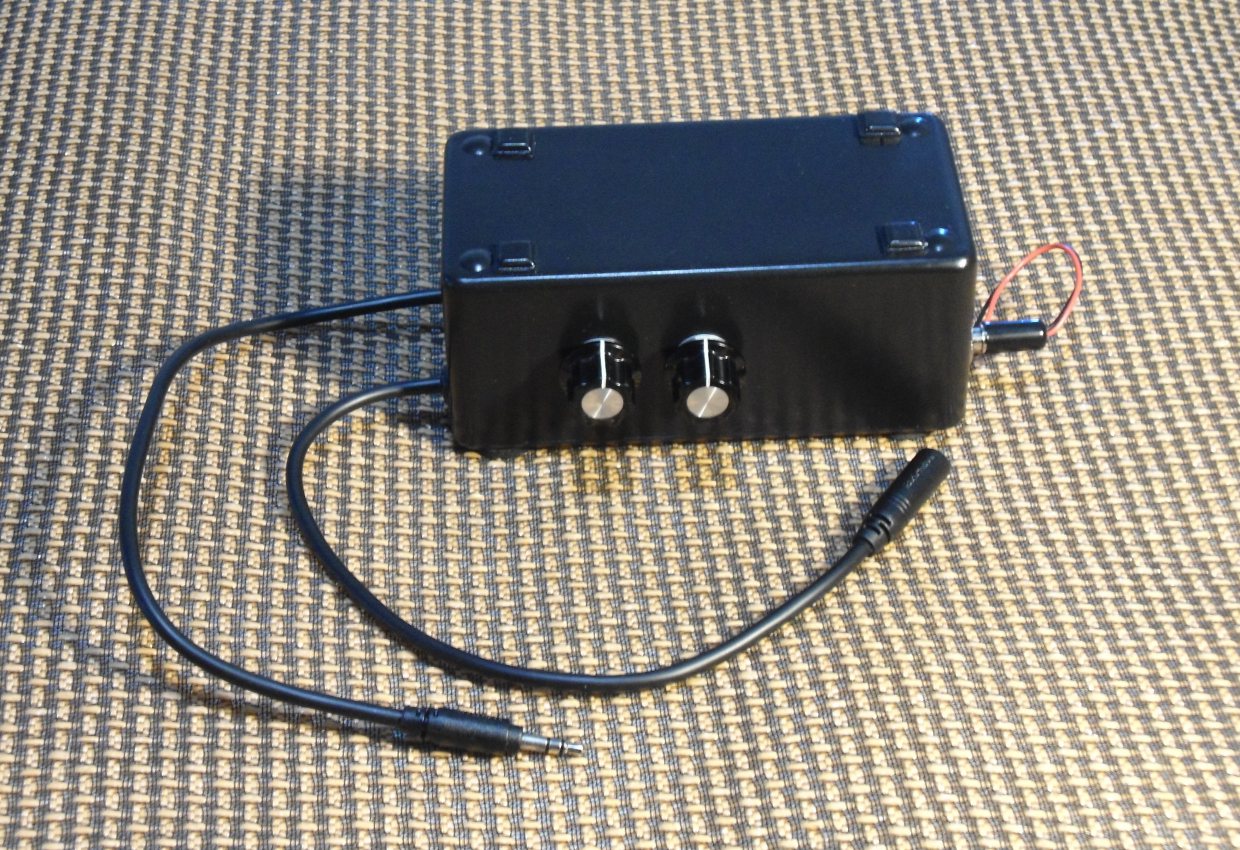
The Bass Bump Headphone Amp has no power switch — you turn it on by inserting the coaxial power plug from the battery clip into the coax jack wired to the amp circuit. In this way two parts perform 3 functions: power switching (jack and plug), battery recharging (battery plug), and external power for the device (power jack). The plug and jack are very rugged. For stationary use, you can also power your Bass Bump from a USB port, using a custom cable we’ll also show you how to make.

The schematic shows one channel. The left side of the schematic is the input and tone control. The right side is the amp section. The signal comes in from the far left.

How It Works

Resistor R8 provides a load for the source device, reducing noise. The input signal splits into two branches. The separation between frequencies happens at about 100Hz, between conventional bass- and mid-ranges. High-frequency sounds pass through the junction of C6/R3, and low-frequency sounds through R7/C5. Series resistors R4, R5, and R6 connect the high-pass and low-pass filter outputs, recombining the frequencies together. Since R5 is a potentiometer, it can be used to control the extent to which high- and low-pass outputs are mixed in the recombined signal. Resistor R4 limits the maximum bass “cut” to about 3dB, and resistor R6 limits the maximum “boost” to about 13dB. Note that R4 and R6 are different values because we’re more likely to want “boost” than “cut.”

The signal from the filter enters the LM386 amplifier chip U1 through pin 3. Resistor R1 provides a ground reference level for the chip input. Capacitor C1 is a filter to ground any high-frequency noise from the source device that makes it this far. The chip is powered by a 9V battery or external power with the supply connected to pin 6. Pin 4 is ground. Capacitor C4 filters noise from the power supply.

Pin 5 is the amp’s audio output. This pin adds a DC voltage equal to one-half the supply voltage (4.5V in the case of battery power, 2.5 in the case of USB) to the audio signal. Capacitor C3 blocks this additional DC voltage from reaching the audio output and passes only the AC audio signal. R2 and C2 form a so-called “Zobel” network to ensure a low-impedance load at high frequencies and to damp oscillations. Resistor R9 acts as a ground reference to keep C3 from charging up and “thumping” when the headphones are plugged in.

Let’s build it!

YouTube player

Project Steps

Prep the enclosure bottom.

Place the PCB in the case bottom, vertically centered and up against the screw posts to one side, as shown.

Use a scratch tool or paint pen to mark through the lower left and upper right PCB mounting holes onto the plastic below.

Drill 4mm holes at both marks.

Mark the circuit board hole positions.

The PCB has 2 identical sections — you’ll use one for the right channel and one for the left. Repeat the following instructions for each of them.

Each section has 20 copper traces, and each trace connects 5 component lead holes. Eight of these traces will hold the chip socket. Others will be used for component interconnections and off-board wires.

Use a fine-tipped marker to number the traces on the copper side of the board (the bottom), as shown, before installing components.

Flip the board over to the component side (the top) and number the traces to match.

Label the 5 holes of each trace with letters “A” through “E,” with “A” at the center of the board and “E” at the outside. Thus the inner hole on the trace at the upper left is “1A” and the outer hole of the trace at the upper right is “20E.”

Finally, mark one section of the board “R” for right and one “L” for left.

Install the socket, electrolytic caps, and jumpers.

Insert the DIP-8 socket for the amp chip into holes 1A–4A and 20A–17A on the topside of the board, orienting the notch in the socket body toward 1A and 20A (“up”). Flip the board over and solder the socket leads to the traces on the bottom.

NOTE: The electrolytic capacitors are polarized and must be installed in the proper orientation. The negative (–) lead is identified by a vertical band on the housing.

Insert the positive lead of capacitor C3 (220µF) into hole 17E and bend the negative lead to hole 15E. Solder and clip both leads.

Capacitor C4 (100µF) will be placed above the chip socket with its leads straddling the “trench.” Refer to the photo. Bend the positive lead into hole 18B and bend its negative lead into 2C. Solder and clip the leads.

Insert and solder jumper wires between positions 8A and 13A, and between positions 2B and 4B.

Insert a jumper wire between positions 4E and 8E, passing it to the outside of the other “E” holes to leave them clear, and solder.

Add the film caps and ceramic caps.

NOTE: These capacitors aren’t polarized, so it doesn’t matter which lead is which.

Insert capacitor C2 (0.047µF) into hole 16C and bend its other lead to hole 13C. Solder and clip the leads.

Insert capacitor C1 (33pF) into hole 2D and bend the other lead to hole 3D. Solder and clip the leads.

NOTE: Attach the following 0.22µF caps 1mm or so above the PCB surface so they can be moved around a bit, later, to make room for resistors. It’ll be a tight fit in spots.

Insert capacitor C5 (0.22µf) into hole 7E and bend the other lead back to hole 8D. Solder and clip the leads.

Insert capacitor 6C (0.22µf) into holes 6C and 5D. Solder and clip the leads.

Add the resistors.

NOTE: All resistors are mounted vertically except R9 and R4. Resistor value tolerances are +/– 10%. For instance if 2K is specified you may use any value from 1,800Ω to 2,200Ω without affecting the performance of the circuit.

Insert R1 (22K) into 3C and bend the other lead down to 4C. Solder and clip both leads.

Insert R2 (10Ω) into 17B and bend the other lead down to 16B. Solder and clip both leads.

Insert R3 (10K) into 4D and bend the other lead down to 5E. Solder and clip both leads.

Insert R4 (10K) between 14A and 5A. Solder and clip the leads.

Insert R6 (2K) into 9C and bend the other lead down to 7C. Solder and clip both leads.

Insert R7 (10K) into 6D and bend the other lead down to 7D. Solder and clip both leads.

Insert R8 (100Ω) into 8B and bend the other lead down to 6B. Solder and clip both leads.

Insert R9 (100Ω) between 13D and 15D. Solder and clip the leads.

Add the off-board leads.

NOTE: Cut all these wires 4″ long and strip 1/8″ of insulation from one end. You’ll trim them to length later.

Solder a black wire to position 13E.

Solder a red wire to position 18E.

Solder a blue wire to position 14B.

Solder a green wire to position 9E.

Solder a yellow wire to position 3E.

Solder a grey wire to position 13B.

Solder a brown wire to position 8C.

Clip off any excess wire on the solder side of the PCB.

Mark and cut the potentiometers.

Hold each potentiometer with the shaft pointing away from you, the flat back facing you, and the solder lugs to the right. Mark the center lug “CT,” the lower lug “CW,” and the upper lug “CCW.”

The potentiometers come with a long shaft that must be cut to length. Start by making a Sharpie mark 10mm up the shaft from the potentiometer body.

Clamp the free end of the shaft in a vise or pair of pliers and use a hacksaw or rotary tool to cut it off at the mark.

Chamfer the cut end with a file. Avoid getting metal particles inside the potentiometer body, which will interfere with its operation.

The potentiometers have small tabs on their front edges for panel alignment. We won’t use be using these, so snap them off with pliers.

Prepare the input and output cables.

Because chassis-mounted jacks are easily damaged I’ve chosen to make input and output connections through captive cables, which are stronger.

Cut a 16″ section off each end of the headphone/computer speaker extension cord to make input and output cables. The plug (male) section will be the input cable and the jack (female) section will be the output. Save the leftover cord for making the charging cable.

Strip 3″ of the black outer casing from the cut-off end of each cable section, and remove the inner foil. Retain the bare silver ground wire.

Cut the ground wire off to ½” and twist the strands. Strip ¼” of insulation off each of the black and red wires and twist the strands.

Slip a black rubber grommet (10mm OD, hole size 8mm, 5mm ID) over the cut end of each cable section.

Install the input and output cables.

Position the input cable between the two holes at the upper edge of the PCB, with the red and black wires pointing toward the center of the board.

Pass a 3mm or 1/8” zip tie (shown red) through the PCB holes and around the cable, positioning the bare ground wire pointing upward away from the PCB. Secure the zip tie tightly around the cable.

Solder the red wire of the input cable to hole 6E of the right-hand section of the PCB.

Solder the black wire of the input cable to hole 6E of the left-hand section of the PCB.

Each section of the PCB has a gray wire attached at position 13B. Trim these to appropriate lengths to reach the input cable’s bare ground wire, strip their free ends, and solder them to the ground wire directly.

Fasten the output cable to the lower center holes of the PCB in the same manner as the input cable.

Solder the red wire of the output cable to hole 15B of the right channel.

Solder the black wire of the output cable to hole 15B of the left channel.

Each section of the PCB has a brown wire attached at position 8C. Trim these to appropriate lengths to reach the output cable’s bare ground wire, strip their free ends, and solder them to the ground wire directly.

Wire the bass control potentiometers.

Solder the blue wire from each channel’s position 14B to the “CCW” tab of the corresponding pot.

Solder the yellow wire from each channel’s position 3E to the center “CT” tab of the corresponding pot.

Solder the green wire from each channel’s position 9E to the “CW” tab of the corresponding pot.

Connect the power input jack.

Pass the red wire from each channel’s position 18E through the PCB mounting hole at the lower right.

Pass the black wires from positions 13E through the same hole.

Cut all 4 of these wires to the same length and strip 1/8″ of insulation from the ends.

Place the bundled washer on the type M chassis-mount jack and install the nut.

Solder both of the black wires to the outside terminal.

Twist together the red wires and solder them to the center terminal of the jack.

Make a battery power cable.

Disassemble the type M coaxial plug and pass the leads of a 9V battery clip through the threaded black housing as shown.

Solder the red wire of the battery clip to the center contact of the coaxial plug. Solder the black wire to the outer “shield” contact.

Crimp the wires in place, making sure not to cut through the insulation. Screw the black housing onto the plug. The cable is ready to use!

Make a USB power cable (optional).

Cut the USB cable to length and carefully strip off about 7mm of the outer casing. This will expose 4 wires of different colors and possibly a layer of metal foil. Cut away the foil.

Retain the red and black wires and clip the other 2 wires off as short as possible so they can’t make contact with anything.

The red wire is +5V power and the black wire is ground. Carefully strip 2mm of insulation from each.

Separate the wires, connect a voltmeter across them, and plug the cable into a USB outlet. You should read +5V.

Disassemble a type M coaxial power plug and pass the cut end of the USB cable through the threaded black plastic housing, as shown.

Solder the red wire to the short center contact of the coax plug and the black wire to the outer “shield” contact.

Carefully crimp the shield clamp around the insulation of the USB wire for a solid mechanical connection.

NOTE: These are delicate wires, so you may want to add some hot glue to reinforce the connections. But don’t use too much, or the housing may not thread back on.

Thread the black plastic housing onto the plug body. The cable is ready to use!

Make a charging cable.

The internal 9V battery can be recharged from a standard 9V battery charger, but because it can’t easily be removed from the case, we’ll recharge it through the plug soldered to its battery clip.

Grab the length of leftover cable from the headphone extension cord, cut it to whatever length you prefer, strip ½” of the outer casing from each end, and cut away the bare ground wires and any foil exposed. Strip ¼” of the insulation from the red and black wires at each end.

Solder the red wire to the center contact of a size M inline coaxial DC power jack.

Solder the black wire to the jack’s outer contact and carefully crimp the collar around the wire.

Slide the jack’s black plastic housing on from the other end of the cable and screw it down.

Slide a 2″ piece of ¼” heat shrink tubing over the cut end of the cable.

Slip a 1″ piece of approximately 3/16″ heat-shrink tubing on each of the 2 wires of a 9V battery clip.

NOTE: Solder the red wire of the battery clip to the black wire of the cable and vice versa. If you match colors here, the polarity will be reversed and the battery will not charge and may actually be damaged.

Slide the smaller pieces of heat-shrink tubing over the battery clip wire solder joints and apply heat to shrink them in place.

Slide the larger piece of heat-shrink tubing down over all the solder joints and apply heat to shrink it in place.

Check the PCB for errors.

Carefully examine both sides of the board, checking against the schematic and photos as you go. On the component side, check that all leads are attached in the correct numbered positions. On the solder side, use a magnifier to look for missed solder joints, cold joints, or accidental solder shorts between traces. This is a tiny board and problems are easily overlooked with the naked eye.

If you think you see a solder bridge between traces, run a knife point between the traces to scrape it away.

If you think you see a missed, cold, or other bad solder joint, apply heat with your soldering iron to “reflow” the existing solder and, if necessary, apply some more.

Test the finished circuit.

Plug the LM386 chips into their sockets with pins 1 and 8 closest to the upper edge of the PCB, as shown.

Snap a 9V battery onto the battery clip and plug it into the power jack.

Turn the potentiometers fully counterclockwise.

Plug the input cable into a music source like an MP3 player and start a track.

Plug a pair of headphones into the output cable.

If everything is working you should hear the audio through the headphones and be able to increase the bass of each channel by turning the potentiometers clockwise.

Tape the enclosure for marking.

Remove the enclosure lid and set it aside. Cover the outside of the enclosure body with white tape on the largest face, the 2 smallest faces, and one of the 2 remaining “long” faces.

With the open side of the box facing downwards, rotate the taped-over “long” face toward your body. Label it “B.” Label the small face at the left end of the box “A,” and the small face at the right end of the box “C.”

Mark the enclosure for cutting.

On face “B,” mark 2 points 25mm from the bottom edge of the box, one each at 37 and 62mm from the left edge.

On face “A,” draw 2 vertical lines starting at the bottom edge. Each line should be 10mm long and 13mm from the near corner. There should be 33mm between them.

On face “C,” draw a vertical line 15mm long starting at the bottom edge. It should be 20mm from the left-hand corner.

Drill and file the openings.

On face “B,” drill an 8mm hole at each of the marked positions.

On face “A,” file out a round-ended slot 6mm wide and 10mm long on each of the lines you previously marked. To help the file run true, try cutting a slot along the line with a saw or rotary tool first.

On face “C,” file out a round-ended slot 10mm wide and 15mm long on the marked line.

Scrape any stray plastic or burrs off the filed and drilled edges with a hobby knife. Now peel off the tape, and the box is ready for final assembly.

Mount the electronics.

Rotate the potentiometers so that the solder tabs face away from each other. Remove the washers and nuts. Pass the potentiometers through the 8mm holes, from inside the box, and secure with their bundled hardware.

Loosen the nut on the chassis mount power jack and temporarily slide it into its slot. Place a square of double-sided adhesive foam tape on the flat end of the 9V battery and install it next to the power jack, orienting the wire from the battery clip toward the enclosure wall. Place the battery as close to the end of the box as possible. Remove the power jack, for now.

Attach the PCB to the enclosure bottom by passing two 6-32 × 1/2″ screws through the holes you drilled earlier, from the outside, through the corner holes of the PCB, and then securing with nuts. Do not over-tighten.

Close the case.

Slide the grommets up the input and output cables and secure them in their slots. It’s a tight fit by design — we’re counting on the compressed rubber to secure the cables in the grommets. Put the bottom on the enclosure, install the 2 screws on the end nearest the grommets, and run them halfway down.

Slide the chassis mount power jack all the way into its slot and tighten the nut with needlenose pliers. Route the wire of the battery clip out of the box through one lower corner of the power jack slot. Install the 2 bottom screws on the end nearest the power jack, then tighten down all 4 screws completely.

Apply adhesive rubber feet over the 4 exposed screw heads on the bottom of the enclosure. I also added small adhesive rubber feet on top of the box so I can set my iPhone there without it sliding off.

Install the knobs on the potentiometer shafts.

Pump up the volume!

Plug the battery cable plug into the power jack and you should be good to go! Note that the battery will be draining any time this plug is inserted, whether the amp is playing music or not.

NOTE: If you use a smartphone as a music source you may occasionally hear ‘static’ through the headphones. A cellphone periodically broadcasts to communicate with the nearest tower and the headphone amp circuit can’t exclude 100% of this noise. It happens most when a streamed file is downloading. Use WiFi to reduce this effect or wait for the track to fully download before playing.

NOTE: I have found that some smartphone earbuds with a 4-contact plug will provide mono sound unless the plug is pulled out about 1mm from the jack. Plugs with 3 contacts do not have this problem.

Optional: Mod the case.

You can show off the insides of your Bass Boost Headphone Amp with a clear top. I used the bundled optional metal bottom of the project box as a pattern to make a top panel out of clear 3mm acrylic. Rough out the acrylic with a saw and sand it to final shape. Drill 3mm holes for the corner screws. Saw and drill slowly because acrylic has a low melting point and will gum up if your tool generates too much friction heat.

Saw off the top panel of the box by cutting around its edge with an abrasive disk in a rotary tool. Sand the cut edge flat and clean up the edges with a knife or file. Use short #3 sheet metal screws to attach the top to the box’s screw post holes. Don’t over-tighten or you may crack the acrylic.

I found that the enclosure could be cut down to as little as 35mm tall. The parts can be fit inside by positioning the potentiometers lower, placing the battery horizontally below the PCB, and wedging the PCB between the side of the box and the back of the pots. It takes a bit of fiddling to make everything fit, but results in a smaller overall package.

The final version shown here is housed in a custom case built from 0.100″ acrylic and 0.250″ polyethylene sheet. Screws through metal tube spacers hold it together at the corners. The potentiometers are smaller than the RadioShack parts to save on space. There is no option for externally powering the unit. The lever switch selects between turning the unit on and charging the battery through the coaxial socket.

Conclusion

To use the charging cable, snap its battery clip onto the contacts of a 9V battery charger, and plug the jack end of the cable into the plug attached to the headphone amp's internal battery. You can continue using the headphone amp while the battery is charging by connecting the USB power cable to the power input jack.

I am indebted to guitar amp wizard Duncan Munro for posting the Tone Stack Calculator app to his website. I used its graphical tone display function as a starting point for calculating the bass filter values used in this circuit. If you are curious about tone filters, you can download the app and experiment with a variety of filter types.