


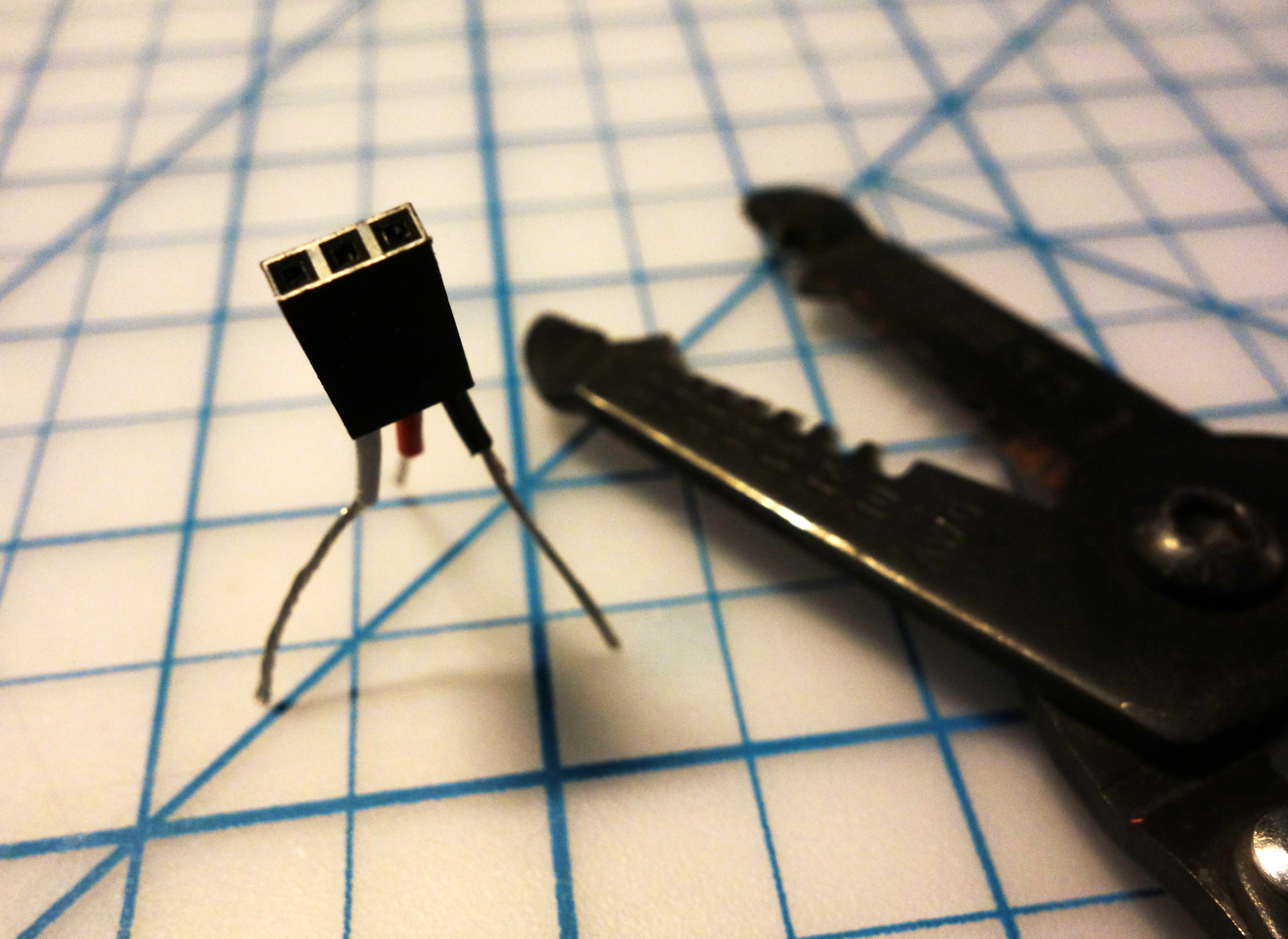
When it comes to transistors, I’m a fan of NPNs (versus PNPs) for their ubiquity and reliability, and because I’ve memorized many of their specifications over time.  Transistors come in many types and packages, and I find myself most-often working with TO-92 package bipolar junction transistors – or BJTs. These are the most-common type of transistors, and TO-92 is short for Transistor Outline Package, Case Style 92. This specifies the three-lead design with the component elements encased in plastic or epoxy; one side is curved and the other flat, usually with some information imprinted on the flat side.
I recently prototyped numerous single-, double-, and triple-transistor FM transmitter circuits. However during the prototyping stage – building circuits on breadboards – I encountered numerous circuits that were acting errantly.
Since I was only prototyping the circuits for fun, a number of the components were not bought new, and instead sourced from my junk drawer. I didn’t plan on building more than one of each of the designs, and was merely building several different designs to compare and contrast features of each circuit.
Some quick multimeter probing lead me to suspect the transistors in my circuits. I attempted to use my multimeter’s mini-hooks to attach to the transistor leads inserted in the breadboard, but some leads were obstructed by other components, and I didn’t want to redesign my layouts simply to test the transistors. I wanted a quicker, more-reliable solution. (Plus not all multimeters have ohmmeters for testing transistors, therefore I wanted something that wasn’t multimeter-dependent.)
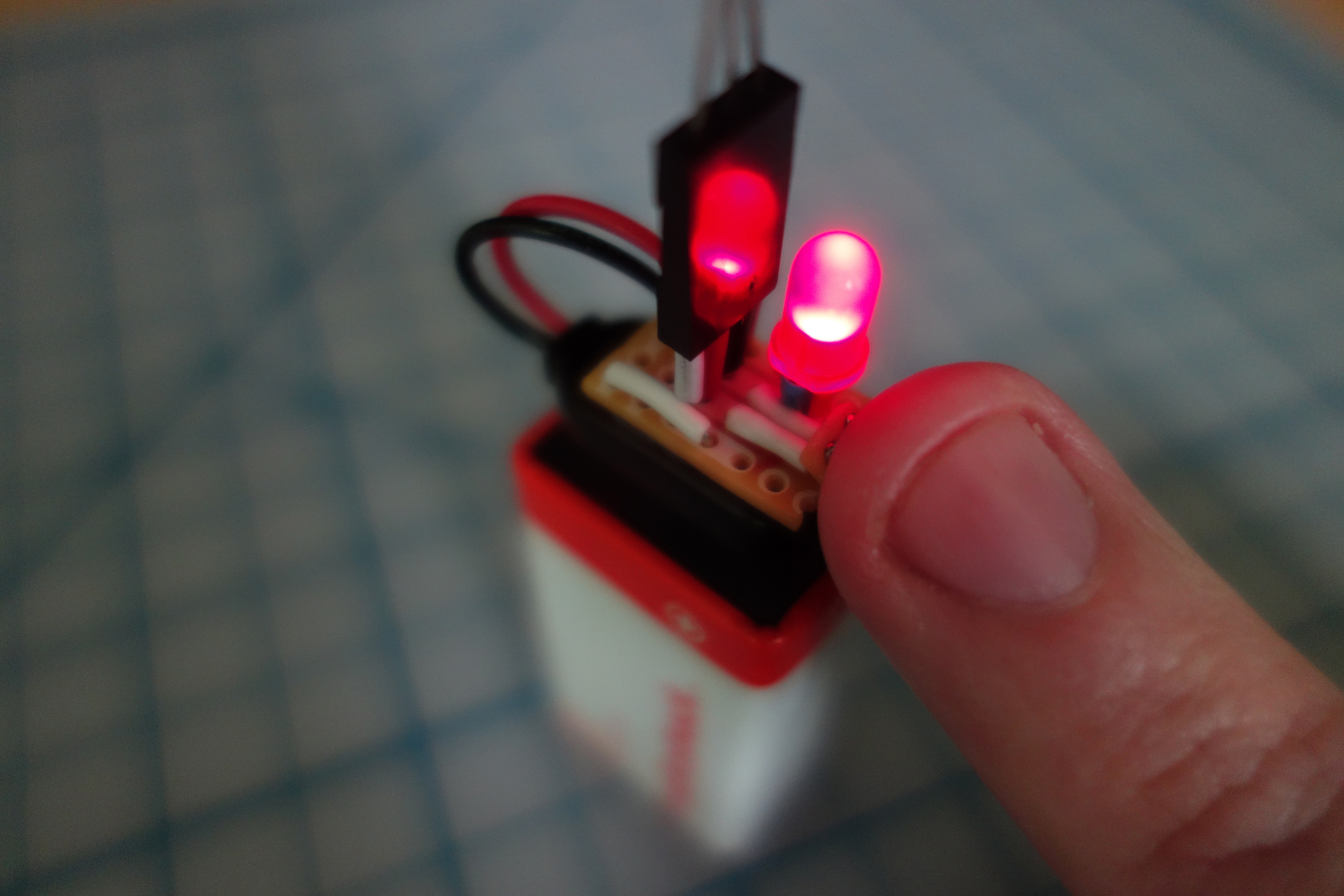
I needed a standalone transistor tester, a simple tool where I could quickly insert an NPN (or PNP, with an easy redesign) transistor, push a switch, and get confirmation that the transistor’s Collector-Base junction was operating correctly.
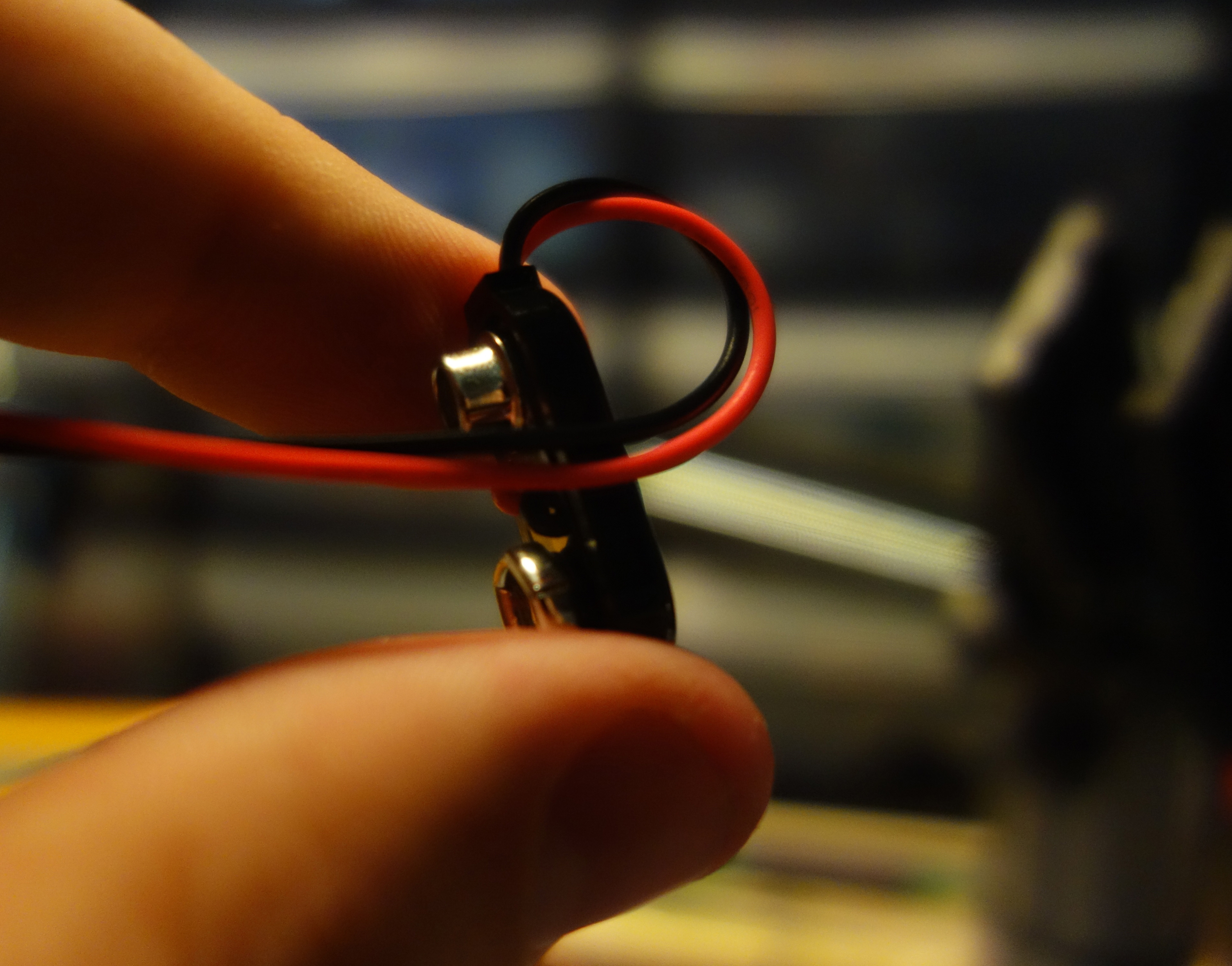
Flipping through Charles Platt’s book Make: Electronics – as I often do for inspiration – I stumbled upon Experiment #10, specifically the Fingertip Switching sub-section. The experiment is accompanied by this image:

I thought, “Aha! Of course.” The finger bridges the Collector-Base junction, allowing electricity to flow through the circuit, from the Collector to the Emitter. In this sense the finger is a lot like a switch, or as illustrated on the following page of the book, a finger pushing a momentary button:

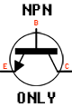
 In the layout above it’s quite easy to see the breadboard design, but here the finger is seen pushing a button, accompanied by a few arrows, letters, and a circle. The hand-finger-button is a stand-in for the transistor’s Base, and the whole illustration is a stand-in for the symbol used to represent NPN transistors in a circuit, seen on the left.
A mnemonic for the NPN transistor’s symbol is the arrow is Not Pointing iN; again as opposed to PNP transistors whose symbol arrow Points iN Proudly.
Now back to Platt’s experimental circuit. The fingertip switch experiment had a few things I didn’t want, and was missing a few attributes I did want. It used 12VDC and if I was leaning towards a tool for my workbench I’d prefer a 9V design. It also included no feedback, no indicator light; in other words it worked, but there was no way to know when it was working. I wanted to add an LED to the design.
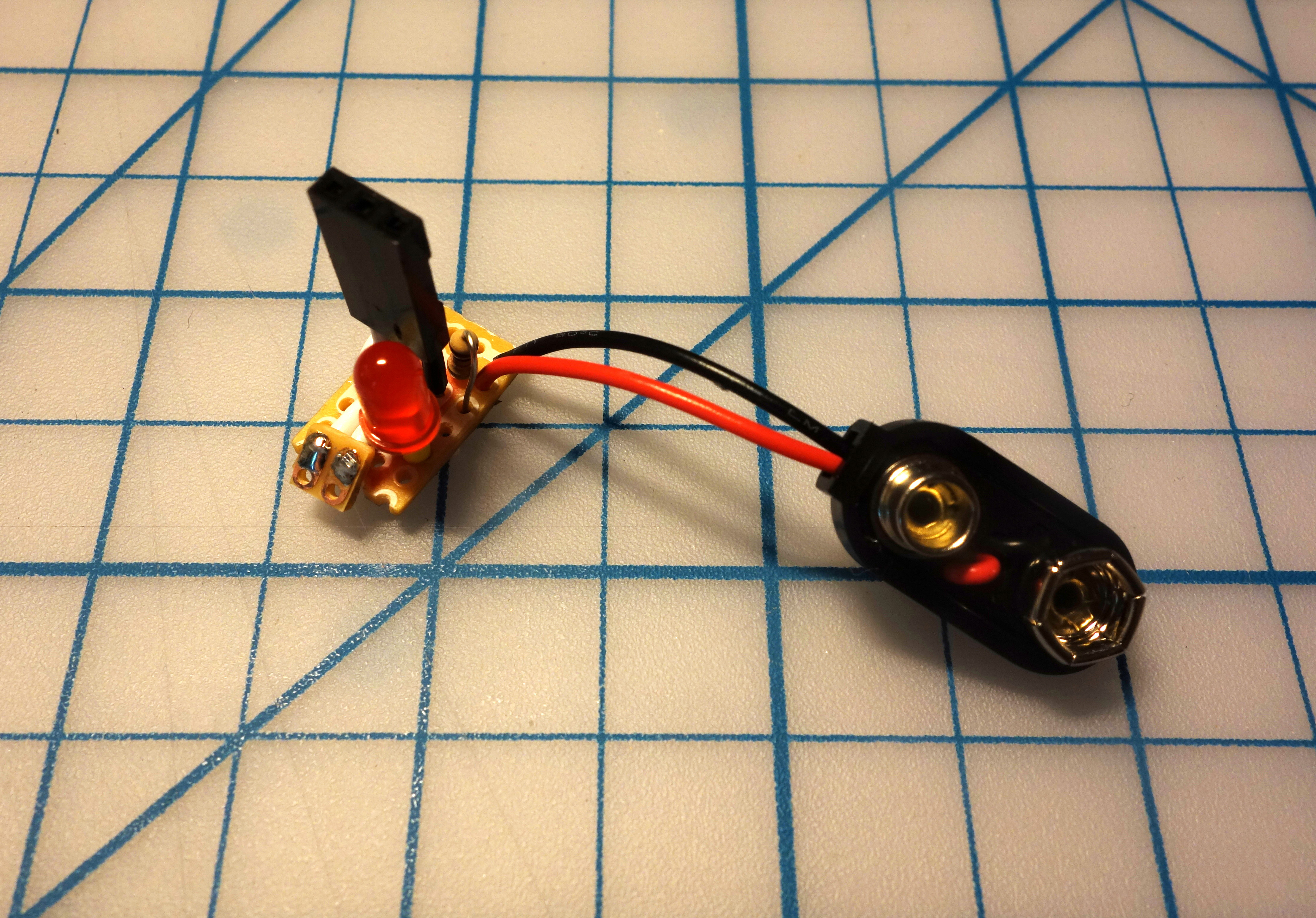
I got ahead of myself and didn’t realize p.75 of Platt’s book also contains a design for a fingertip switch using an LED, but by then I had sifted through a few resources and sketched a few simple designs. Many are similar, and this is the one I settled on:

You can breadboard this circuit in only a few minutes:

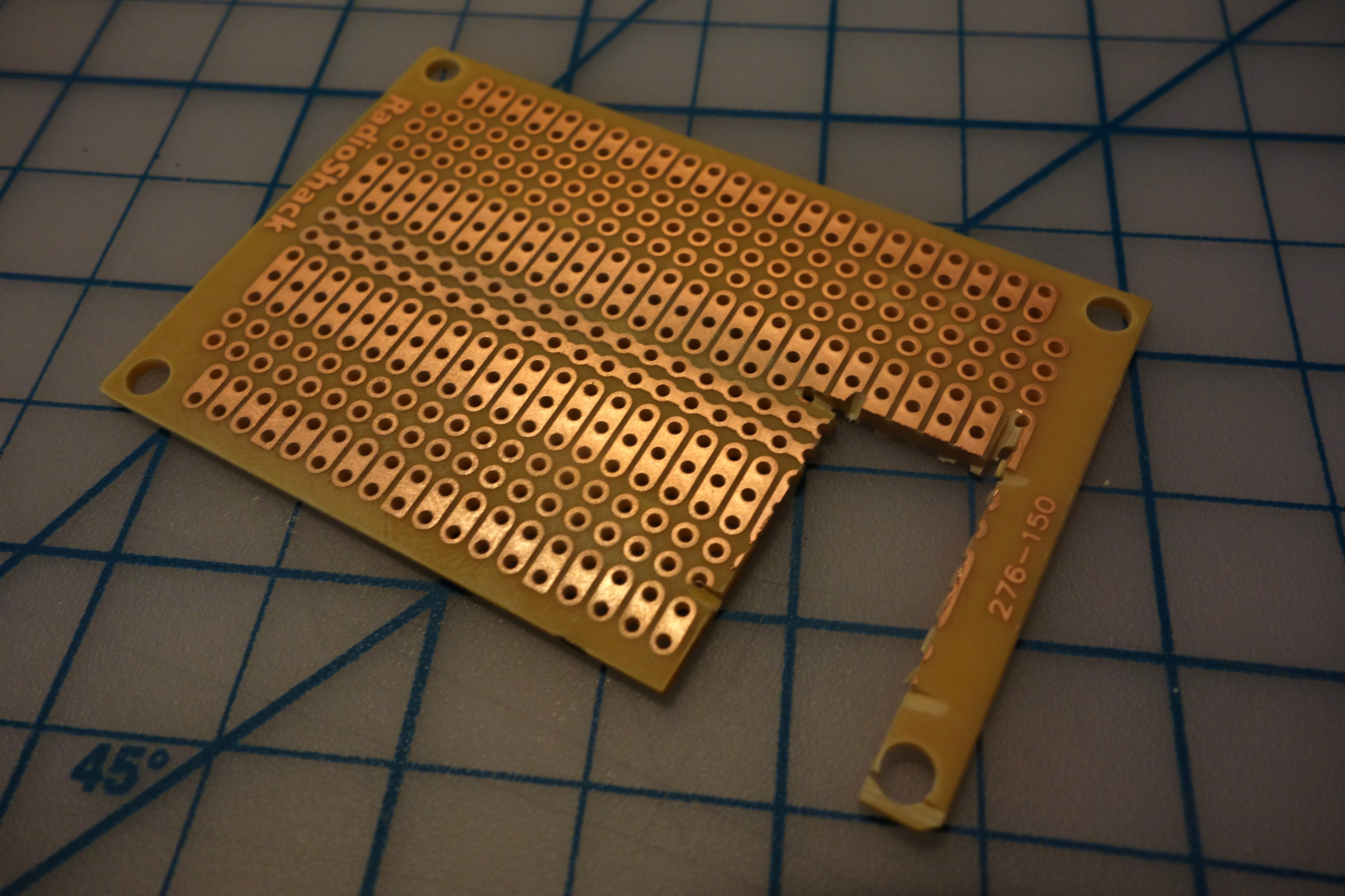
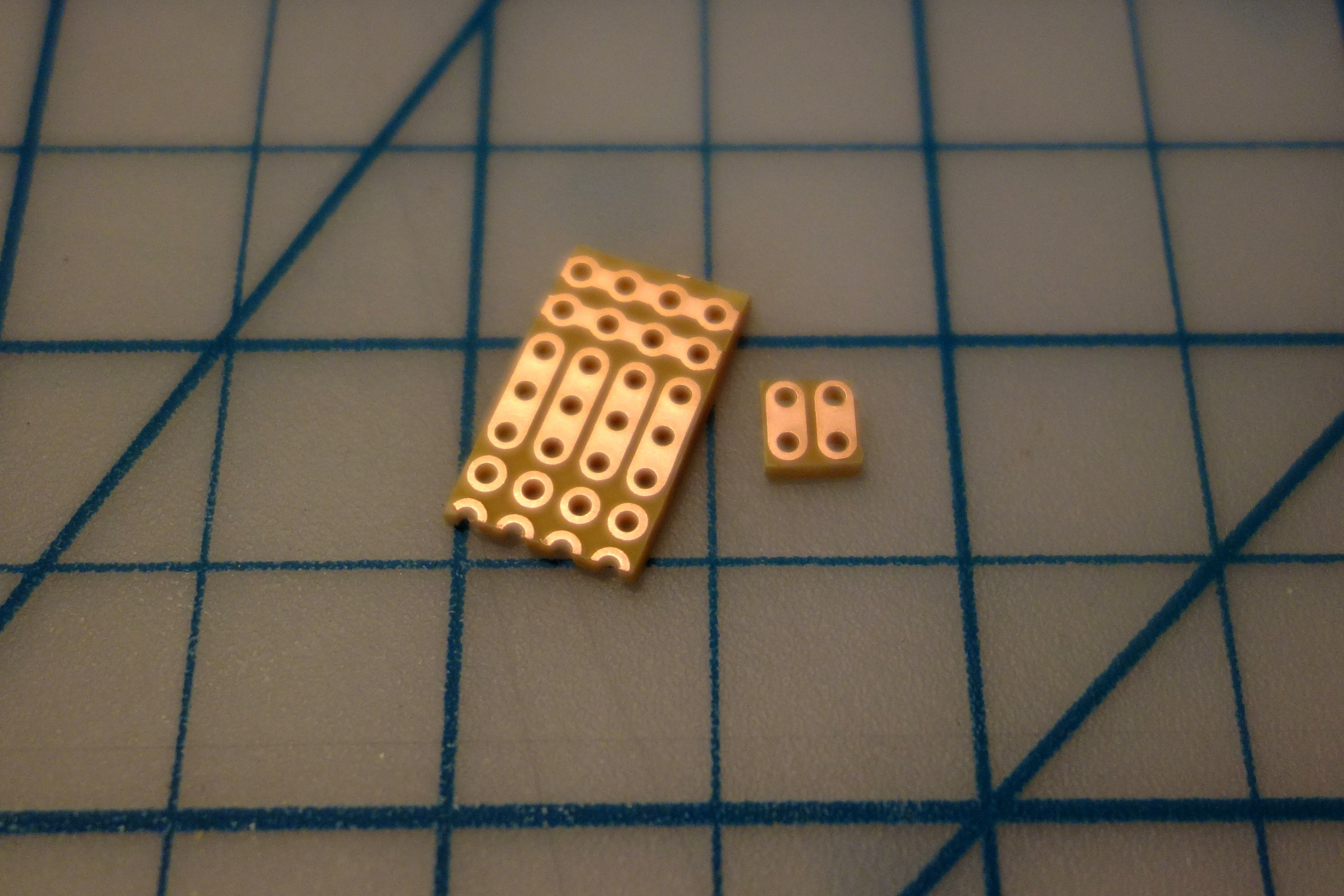
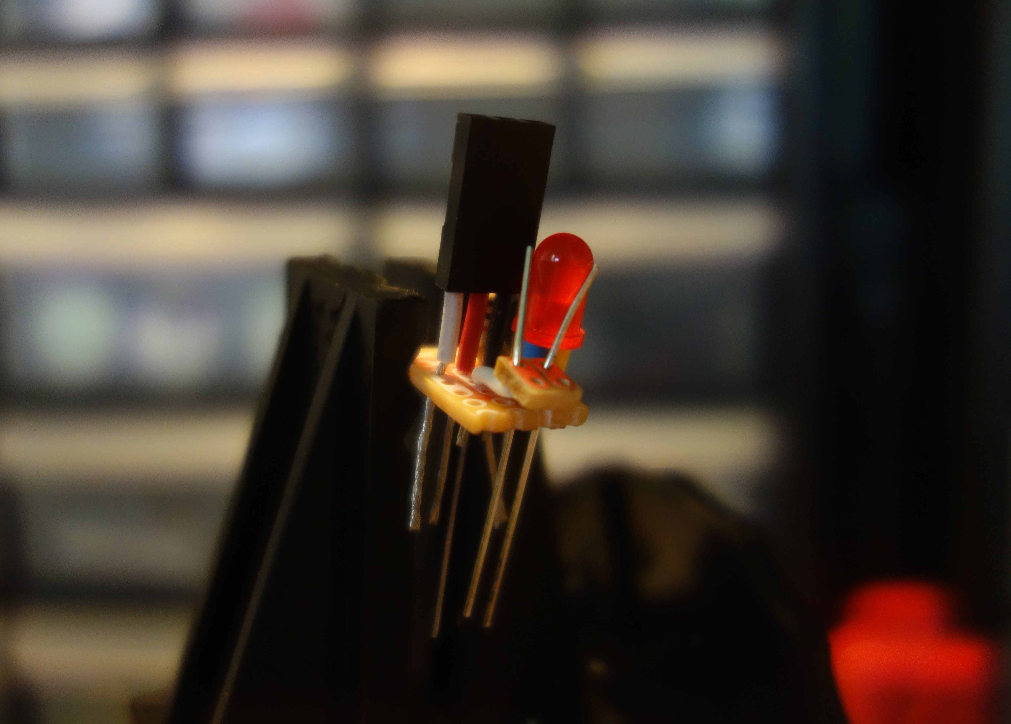
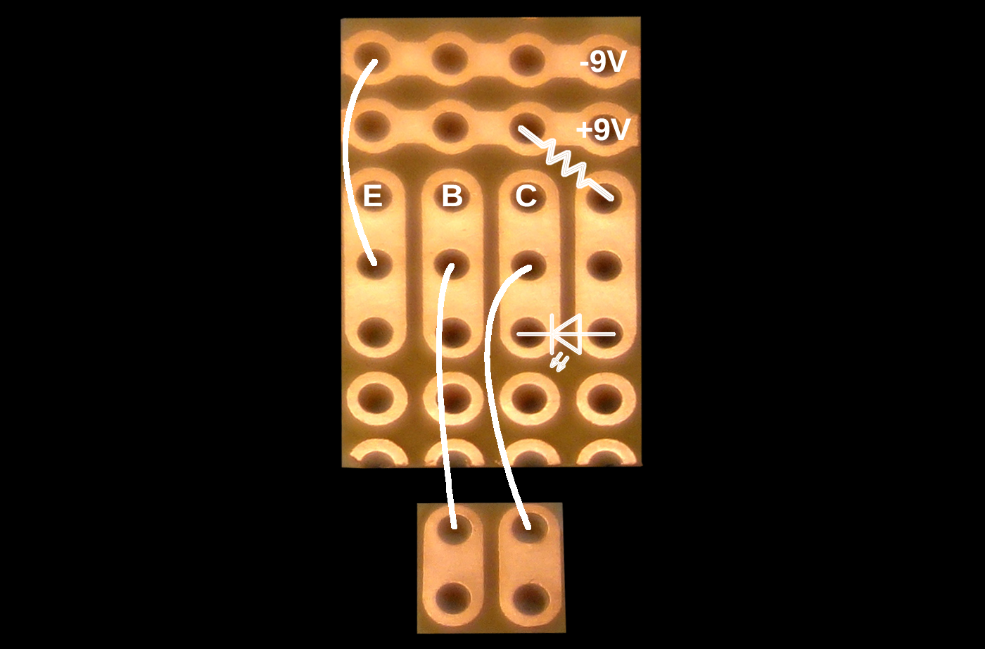
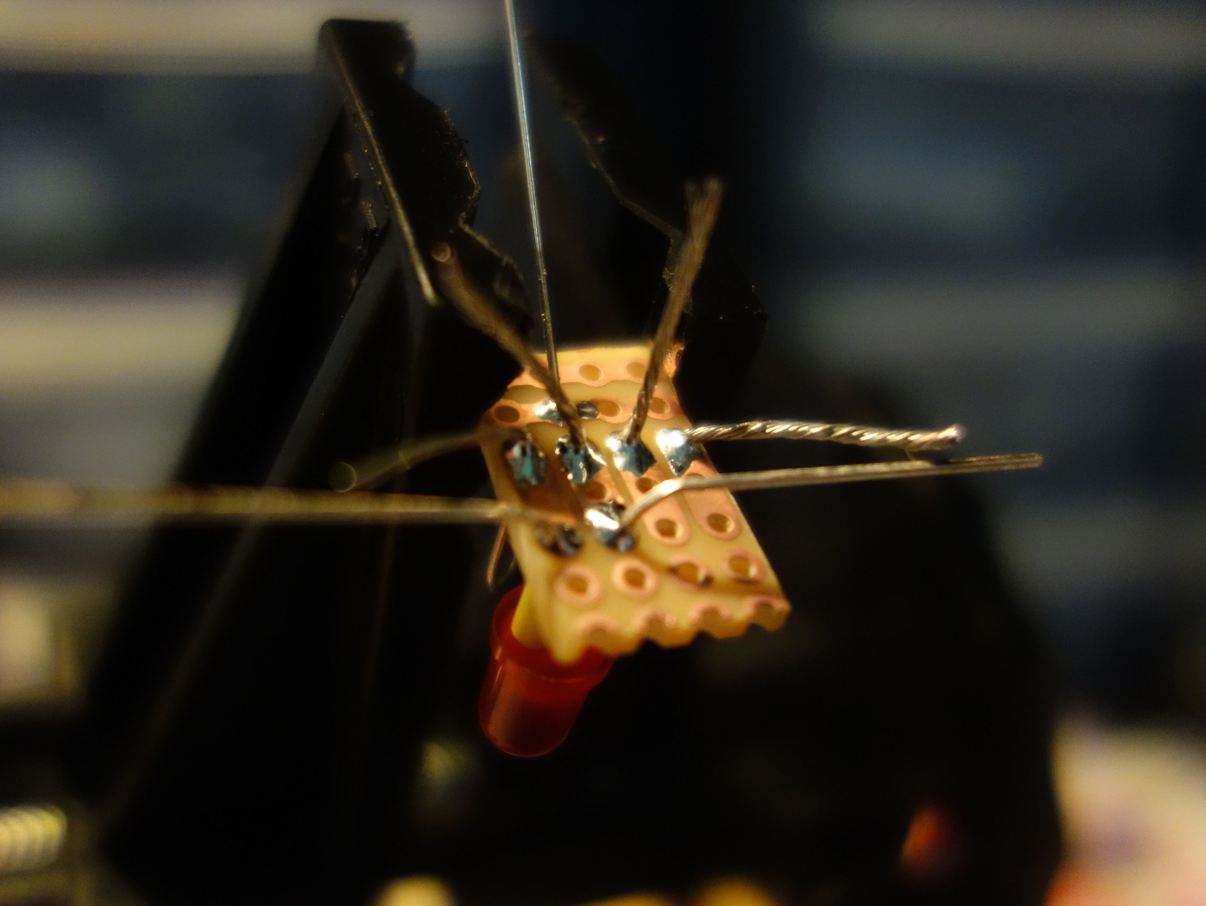
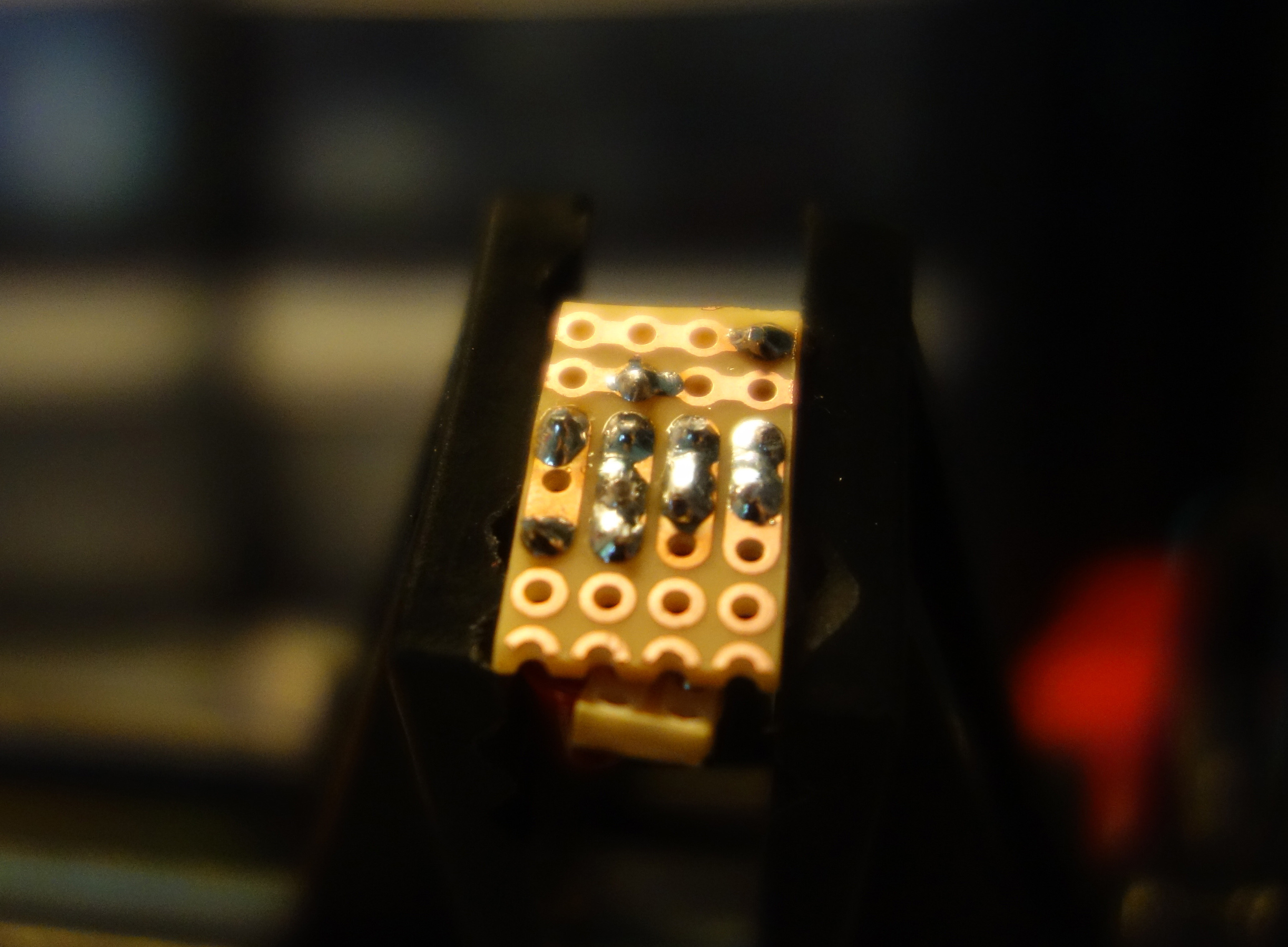
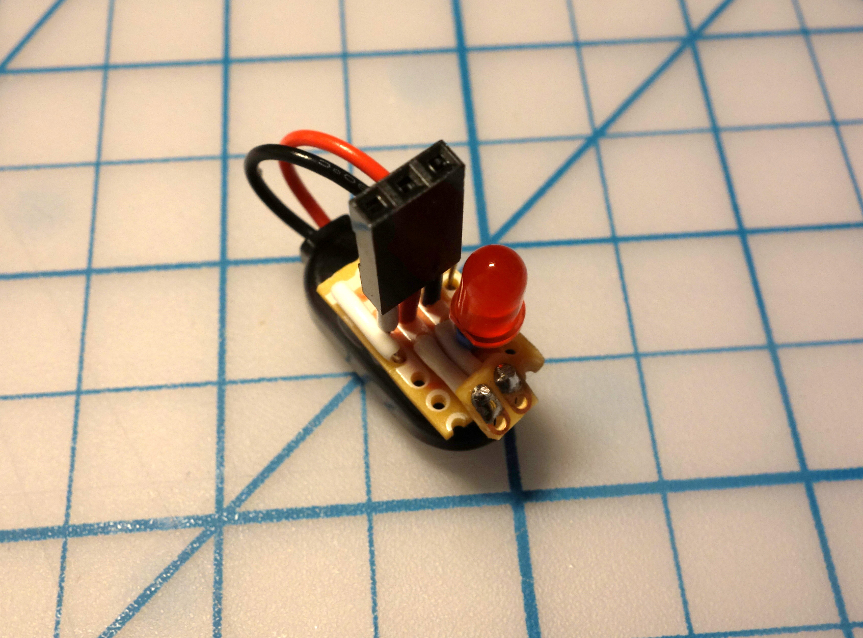
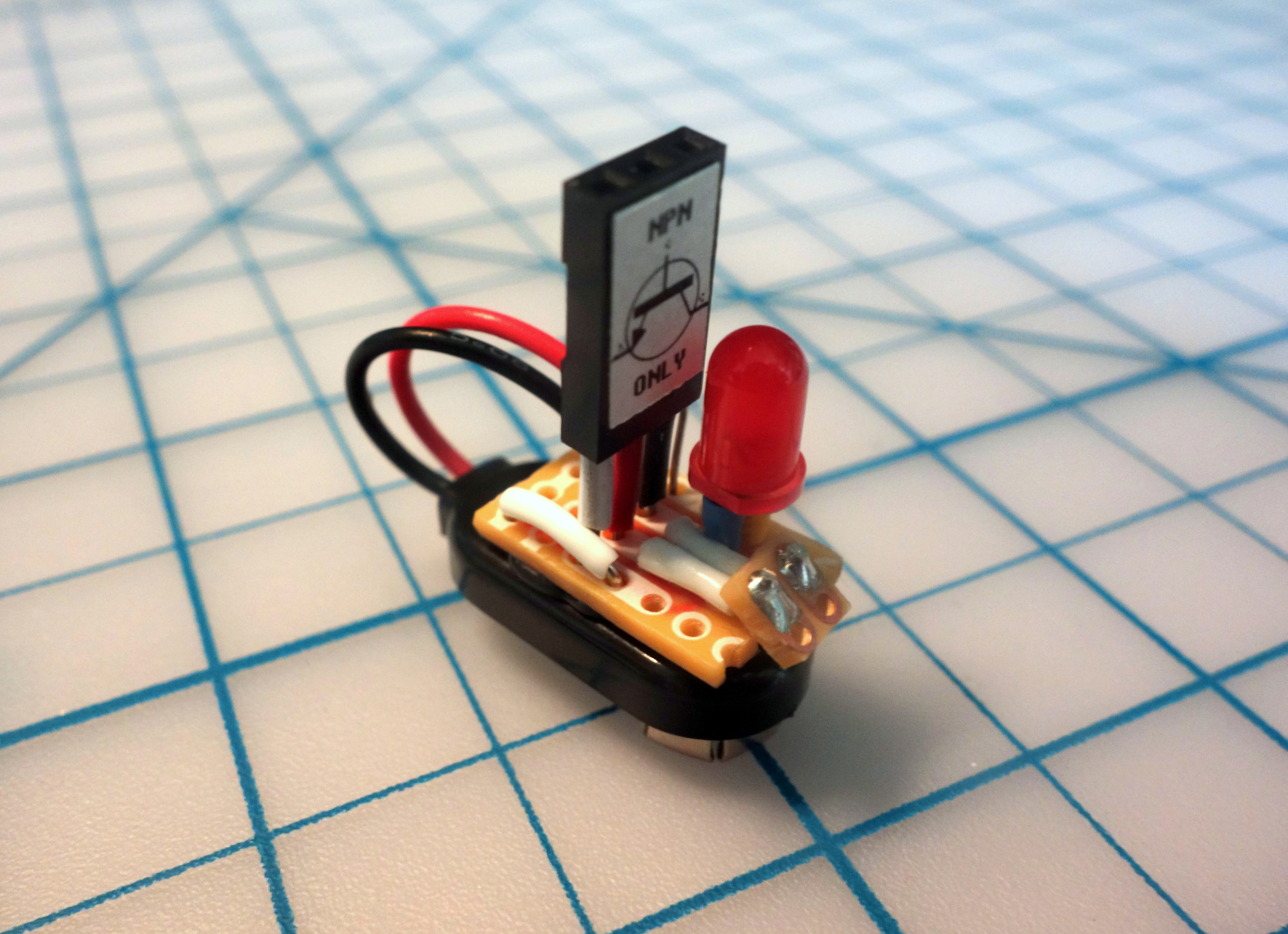
Of course, I also wasn’t going to keep the circuit permanently mounted on a breadboard. I prefer having a tool that I can quickly reach for whenever I need to test TO-92 package NPN transistors. I sketched a few designs, looked at a few available PC board layouts, and settled on what you see below for this Battery Clip Transistor Tester. I designed it to be small enough to mount directly onto a heavy-duty 9V battery clip (as opposed to the “insulated” clips whose wires are encased in a soft nylon pouch). I hope you enjoy building this super simple tool – if you use a lot of NPN transistors in breadboard or through-hole circuits this tool may save you a lot of frustration.


.svg)