figure-0

CAUTION: This project is a non-weatherproof adapter box for 240V. It is not intended, nor should it be used in wet weather or as a permanent installation. Weather-rated parts and ground-fault circuit interrupter (GFCI) components must be correctly and consistently used for outdoor use. Do not consider anything that you learn by reading this project sufficient to perform permanent electrical work like adding breakers, circuits, or outlets. Electricians have to put in tens of thousands of hours on the job to get their licenses for good reasons. Use a licensed electrician for any new electrical installations or modifications to existing wiring or circuits and have the work permitted and inspected according to your local codes and regulations. Use the information and instructions contained in this project is at your own risk.


When I bought a 240V MIG welder and its plug didn’t fit my 240V AC outlet, I went online and bought a custom adapter for it.

When I bought a 240V plasma cutter with a different plug, I bought a different adapter.

When I bought my 240V TIG welder and the problem emerged again, I knew it was time to think like a maker, not a consumer, and build myself a general solution to my problem.

Figure 1 – My plethora of plugs
Read articles from the magazine right here on Make:. Don’t have a subscription yet? Get one today.

There are a huge number of 240V plug/receptacle configurations approved for use in the United States. Other than the world of 3-phase power (which is outside the scope of this project), all of them provide various combinations of 2 hot wires, a neutral wire, and a ground wire. Each of them is rated for a specific amperage. Some are locking and some are straight plugs. My recent skill builder in Make: magazine, “Understanding 240V AC for Heavy Duty Power Tools,” provides a deep dive into the world of 240V, and I hope everyone interested in working with high voltage will read it and expel the surprising number of urban myths and misconceptions that surround this powerful resource.

240V is intimately related to the 120V we know and love for the majority of our AC electrical needs. Some, but not all, configurations of 240V receptacles provide the wires required for breaking out 2 independent 120V circuits. Since my access to 240V is a weatherproof RV style outlet near my driveway, my welding, cutting and grinding occur outside as well. I don’t have a 120V outlet outside, so there is an electrical cord running through my dog door whenever I’m working. This didn’t make anyone happy, so when I decided to fix my 240V adapter problem, I wanted to include 120V outlets as well.

Before we get started, let’s talk about amperage. When considering amperage, think about it in terms of how much is available (the circuit’s rating,) and how much might be used. If you connect a tool that draws 45A to a circuit rated for 30A, ideally you’ll trip the breaker. But you’re also likely to be pulling more current through the circuit’s wires and components than they are rated for until the breaker trips. People rarely run wire rated for 55A on a 30A circuit. If the breaker fails or is slow to trip, you’ll be attempting to turn the wires in your walls into heating elements. Always use equipment rated appropriately for the ampacity of the circuit you’re plugging into.

High amperage circuits are a little bit like being handed enough rope to hang yourself. If you have a tool rated to use 25A, it usually has a 30A rated plug. If you use an adapter to connect this to a 50A circuit, you’ve possibly put your tool at risk. If something happens that causes the tool to draw 45A, the tool and its plug may begin to overheat as their current carrying capacity is exceeded. The tool expects to have a 30A circuit breaker upstream of it, to protect against this. But the 50A breaker thinks everything is fine and will happily continue to overload the poor tool.

The bottom line is to always use components with appropriately matched ampacity. As you’ll see in this project, when we want to make an adapter to connect a 30A plug to a 50A outlet, we add a 30A breaker in line. When we want to split out 120V circuits from the 50A outlet, we have 15A breakers on each 120V circuit so that 50A isn’t made available to the tools we plug in.

Designing the Adapter

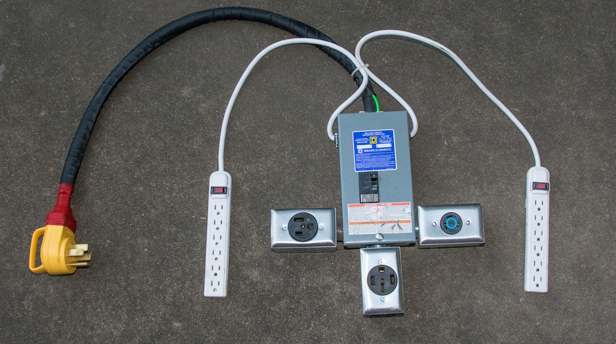
As much as I’d like to have a “universal” adapter, the reality is that there are too many possible configurations to support. I’ve decided to support the set of plugs that my current tools use and get two 120V circuits in the bargain. I’m connecting the adapter to a 14-50R 50A RV outlet which provides sufficient amperage and wiring for my requirements.

So the plan is…

Input:

  • 14-50P 240V 50A plug

Outputs:

  • (1) 6-50R 240V 50A receptacle
  • (1) 14-50R 240V 50A receptacle
  • (1) L6-30R 240V 30A receptacle
  • (2) 120V 15A power strips with breakers

You may want to draw power from a different kind of connector, or you may need different outlets. Please read my accompanying Skill Builder, “Understand 240V AC for Heavy Duty Power Tools” to get a better understanding of how to safely modify this project for other connectors. For this project’s connectors, the relationship is straightforward (see Figure 2).

Figure 2 – Electrical relationship of outlets

If we rearrange that diagram a little, we can derive the schematic for this project. It’s pretty simple, at least compared to the printed circuits I build. (See Figure 3)

Figure 3 – The wiring diagram for the adapter

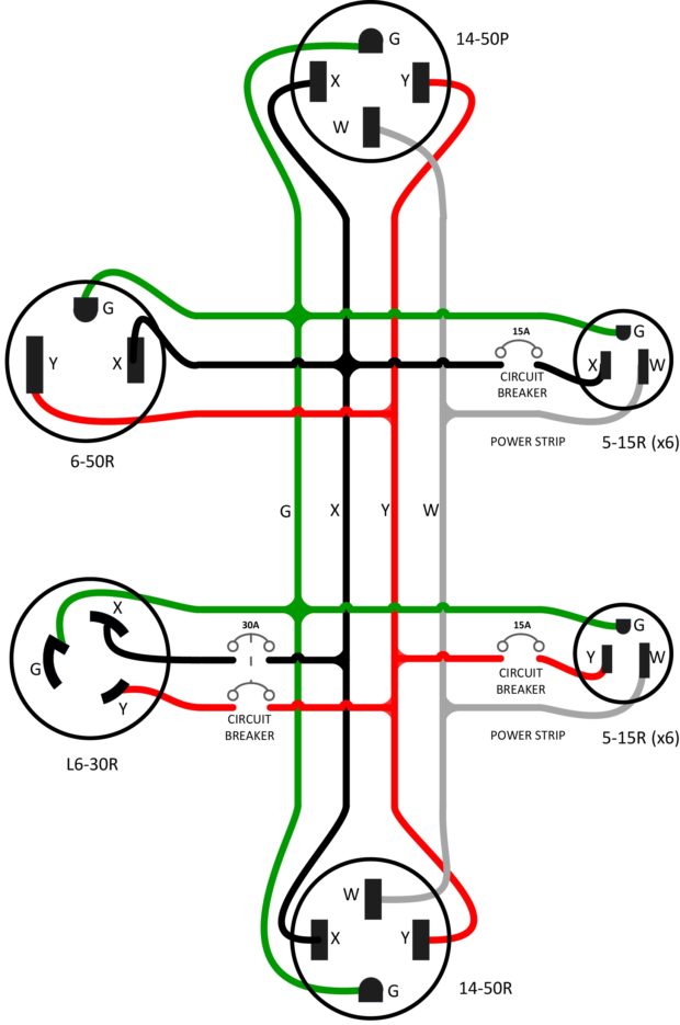
Power comes in through the 14-50P and we get two hot wires (X & Y), a neutral wire, and a ground wire. 240V is available between X & Y and 120V is available between either X or Y and neutral. All these outlets (and all current NEMA 240V connectors) provide ground — it’s an emergency return path for current if something fails. The L6-30R, locking 30A outlet, has a 240V 30A dual circuit breaker protecting it (E3) (see Figure 4). As noted, I’m using 120V power strips that each have an integral 15A breaker (E2) (see Figure 5.)

Figure 4 – 240V 30A dual circuit breaker
Figure 5 – 120V power strips with plugs removed for use in the adapter

Since we need to do a considerable amount of wiring and mount the circuit breaker, I’ve used a “70 Amp 2-Space 4-Circuit Indoor Main Lug Load Center with Cover” (C1) (see Figure 6.) This is a metal box designed to hold two circuit breakers, or one dual breaker. It has mounts for a ground bar (E1) and knockouts we can use to attach our receptacles and incoming plug.

Figure 6 – 2-space breaker box

Project Steps

STEP 1: OPEN THE KNOCKOUTS FOR THE NECESSARY OPENINGS

Electrical boxes generally have openings that are called “knockouts.” This is because the holes remain covered with partially perforated circular discs that you knock out to allow access. Many knockouts have a series of concentric rings, allowing you to choose the desired size by how many rings you knock out. Opening a knockout involves bending the disc or ring in on one of its tabs and then working it back and forth until it drops free. (See Figure 7)

Figure 7 – Knocking out the top hole

For this project we’ll knock out a 1¼” hole at the top, bottom, and bottom left and right. We’ll also knock out a ⅞” hole on the top left and right. The holes will be used as follows:

  • Top: passage for cord from plug, 1″ cable clamp
  • Top Left, Top Right: passage for cords from power strips, ⅜” cable clamps
  • Bottom Left: connection for 6-50R receptacle box, 1″ conduit nipple
  • Bottom Right: connection for L6-30R receptacle box, 1″ conduit nipple
  • Bottom: connection for 14-50R receptacle box, 1″ conduit nipple

STEP 2: ATTACH THE RECEPTACLE BOXES AND CABLE CLAMPS

Once the holes are knocked out we’ll add the receptacle boxes and the cable clamps. The block diagram below (see Figure 8), details the order of the bushings and lock nuts on the cable clamps and the conduit nipples that connect the receptacle boxes.

Figure 8 – Block diagram showing how to connect the conduit nipples and cable clamps

The receptacle boxes will come with plugs to screw into the remaining open holes. Thread these tightly in place. (See Figure 9)

Figure 9 – Plug in the bottom of the receptacle box

For the conduit nipples (C6), thread two lock nuts (V3) onto the center of the nipple. Place one end of the nipple into the breaker box, thread a lock nut on the inside and tighten until the nipple is secure. Add a plastic bushing (V2) on the end and repeat for the receptacle box on the other end of the nipple. The cable clamps (C2) have a rim that sits flush against the outside of the breaker box, so you only need a lock nut on each and a bushing on the inside of the 1″ clamp. (See Figure 10)

Figure 10 – Cable clamp connections

STEP 3: INSERT THE GROUND BAR AND BREAKER

Next we’ll attach the ground bar (E1). This is a metal bar with holes drilled through it and screws across the top. It will be where we will connect all the ground wires to one another. There should be two holes on the top that don’t have screws, and a mounting screw that came with the kit. There was only one mount point in the breaker box I chose, but that works fine. Attach the ground bar to the mount point on the upper left of the box.

We can now snap in the dual breaker (E3). Orient it so that the horizontal contacts on the bottom are on the round rail in the breaker mount and the dual vertical contacts are on the bus bars. Push the breaker firmly down until it snaps in place. Our case is now ready for wiring. (See Figure 11)

Figure 11 – Breaker box with attachments, ground bar and circuit breaker

STEP 4: PREPARE THE INCOMING WIRE FROM THE PLUG

Since I hope you’re reading this article all the way through before going out to buy all the parts, I’ll offer you a shortcut to skip this step. I chose to wire a plug onto the end of the cable so that, if necessary, I could change it out at a later date for a different kind. This is arguably the hard way to do this. For similar (or in some cases less,) money you can buy a 14-50 replacement appliance power cord that has the plug already attached. If you do, be careful, many of these are rated for 40A or less than the full 50A of a 14-50 connection. Use a cable rated for a full 50A.

Because the plug gets a lot more motion over time than the internal wiring, I wanted to use stranded outdoor wire. Solid core or limited strand wire doesn’t handle being bent and moved a lot. My local big-box hardware store sold some lovely 6-3 rubber coated wire that was almost perfect. It has three 6-gauge wires rated for 55A (W1). Unfortunately, the 14-50P plug (E4) is a four wire plug with hot-hot-ground-neutral. It’s usually wired with cable that has three 6-gauge wires for hot-hot-neutral and a 10-gauge wire for ground (which is what I purchased to pull apart for the internal wiring). I liked the stranded, rubber coated wire so much that I decided to add my own 8-gauge ground wire (W4) (see Figure 12). This had the disadvantage of throwing off the standard wiring color scheme since the three wires in the cable were black, white, and green which are traditionally supposed to represent hot, neutral, and ground respectively. I needed the three 6-gauge wires to be hot-hot-neutral, so I made green wire take the place of red for the second hot wire.

Figure 12 – 6/3 cable with added 8-gauge ground

Strip 2½” of the rubber outer shell off one end of the plug cable and 3″ off the other. This is tricky to do without nicking the insulation of the three internal wires. I use a utility knife and make a cut around the insulation that doesn’t go through. I then bend the cable to open up the cut and just touch the edge of the knife into it. If the knife is sharp, the rubber will part and you can continue to do this until you’re all the way through. You may be able to slide the rubber insulation off, or you may have to make a lateral cut to get it off. Be aware, the wires inside are covered with corn starch or somesuch white anti-chafing powder. When you pull the rubber insulation off, it’s going to make a small mess.

The 3″ stripped section goes into the breaker box. The wires that connect inside the breaker box will need to be of different lengths because the white neutral wire has to attach farther inside to the neutral bus. Cut the black and green wires so that they are 1¾” inches long (the white remains 3″,) and strip ½” off the ends of all three wires from the cable and the ground wire. (See Figure 13)

Figure 13 – Breaker box end of the prepared cable

For the wires that will connect to the 14-50P plug (E4), the white wire will be shorter than the black and green. Cut the wire so that it is 2″ (the other two wires remain 2½“). Strip ½” of insulation off the ends of all three wires. Leave the ground wire that will go into the plug unstripped. We’ll need to trim it to length when we assemble the plug.

STEP 5: MOUNT THE CABLE INTO THE BREAKER BOX

The 1″ clamp connector connection (V1) for the rubber cable and additional ground wire is just barely large enough to allow them to pass through. It’s possible that you will disagree with me about whether they fit at all as you struggle to get them to pass through. In my defense I offer some photographic proof that it can be done (see Figure 14).

Figure 14 – Cable entering breaker box

My recommendation is to put the ground wire through first. Then insert the rubber cable and use a twisting and pushing motion to get it in sufficiently to allow the white wire to fully insert its stripped end into the neutral block connector. During the course of stripping and pushing the wires, I managed to very lightly nick the insulation on the black and green wires. I didn’t go even half way through, but as a safety precaution, you’ll notice that I added some silicone tape over the nicks to make sure future problems were nipped in the bud.

The ground wire will connect to one of the terminals on the ground bus. The black and green wires do not go into the bus connectors on the breaker. We have to share their power so we’ll be connecting them to a variety of other wires before connecting to the breaker.

STEP 6: MOUNT THE 14-50P PLUG ONTO THE OTHER END OF THE CABLE

You may have noticed that we have 12″ more of the ground wire than we do the cable. This is because the ground wire has a farther run to reach all its connections. You probably won’t need the entire extra foot, but you’ll need enough to allow the ground wire to reach the ground bus in the breaker box and the ground lug at the top of the plug.

Before we attach the plug onto the end of the cable, slide the heat shrink tubing (W5) over the cable and ground wire. Trim the heat shrink so that it leaves about 2″ of the cable and ground wire clear. There are a variety of ways to apply heat and get the full compression of the heat sink. The best is to use a heat gun with a curved adapter to apply the heat evenly around the cable. You can use a torch, but be careful to go slow and not allow hot spots to damage the heat shrink.

Position the black, green, and white wires so that their stripped sections overlap the lugs they will connect to and route the green ground wire around the inner wall of the plug until it overlaps the lug at the top. Note where this is on the ground wire and cut it at that point. Strip ½” off the ground wire.

The lugs will pull out of the plug so that you can loosen the clamp screws and attach the wires (see Figure 15).

Figure 15 – Wires attached to plug lugs

Pay special attention to the wiring and the orientation of the clamping screws. The lugs have small protrusions on them that will allow them to remain in place when firmly pushed through their openings. Attach the bottom clamp onto the cable and tighten as strongly as you can. The cable will have a tendency to try and pull out of the plug as you use the adapter. Tightening this clamp is your first line of defense against yanking the cable out of the plug.

You really do need to make sure that you completely tighten the clamps that connect the wires to the lugs, trim any excess exposed wire, and fully insert the lugs through the openings. While we’ll add one more layer of defense before we finish, having the cable yank out is, to say the least, extremely undesirable. If things go badly, you can end up shorting wires carrying 240V as they pull off the lugs inside the plug. Tighten everything as strongly as possible. This includes the cover when you screw it back on.

The last line of defense is to take a roll of silicone tape (V4) and use the entire roll to wrap around the cable and the base of the plug. Silicone tape fuses to itself and will form a thick, solid grip that holds the cable in place in the plug. For silicone tape to fuse well, it needs to be stretched while being applied. Hold the end in place and stretch the tape out as you wrap around and around the cable and base. (See Figure 16)

Figure 16 – Cable and plug wrapped in silicone tape

STEP 7: WIRE THE 120V POWER STRIPS

Any type of power strip that has a built in circuit breaker on it will work for this project. I used the cheapest I could find (E2). Most power strips come with a 15A breaker, but if you can find ones with a 20A breaker, that will work just as well and give you some more headroom. Going higher than 20A with 120V should involve using a different connector configuration than the standard ones we see in the walls around us. They’re pretty uncommon, the only one in my life is on my generator, it’s a circular locking outlet (an L5-30R to be specific.) Outside of RV’s and boats, I’ve never encountered anything that uses it.

Cut off the plugs and remove the outer insulation to expose 4″ of wire on one of the outlets and 6″ on the other one. The lengths you expose aren’t critical, but you’ll need to have sufficient neutral wire to reach from the cable clamp around to the neutral block on the side of the breaker mount. It’s farther from one side of the box than the other. Slip the stripped wires through the cable clamps with the shorter stripped section on the side closest to the neutral block so that the end of the outer insulation comes just inside the box.

Lay out the white wires so that they route to an empty location on the neutral block and mark them (remembering to add enough length to let the section you’ll strip go inside the connector.) Cut any excess wire and strip ½” off the ends. Do the same for the green wires, routing them to the ground bus. The black wires will participate in a great meeting of wires in a big copper connector later, so for now, cut them off at 3½” and strip ½” off the ends as well. Put the white and green wires into their connectors and tighten the clamping screws.

STEP 8: PREP THE OUTLET WIRING

The 6/3 indoor wire we bought (W3) is for use in wiring up the outlets. Since this wire is rated for 55A, we could technically use a lighter gauge for the 30A circuit being fed by the circuit breaker. But we have enough of the heavier wire and only using one type is a bit simpler, so it just adds safety margin in this instance. The solid copper wire is frustrating to work with in short runs, it’s hard to bend. If you want to spring for stranded wire, as long as you use the appropriate gauge it’s fine. The solid wire’s advantages are that it is a cost effective approach and tends to have a slightly smaller diameter with insulation. This is an issue when trying to get three wires and a ground through the 1″ nipple, so keep that in mind if you use a bigger wire.

We’re going to cut three 12″ sections of wire (black, red, white, and bare copper), from the 4′ section we purchased. I purchased (and recommend,) 5′ so that you can cope with mistakes. If you don’t make mistakes, you can purchase just 3′. I need 5′. Cutting the 6/3 cable without heavy shears can be a fight — it’s easier to strip off the outer insulation and cut the individual wires to 12″ lengths. You’ll end up cutting these again when you get them positioned, so you’ll need heavy wire cutters to get through the 6-guage copper.

Each of the outlets have screw terminals on the back side. The ground and, if present, neutral should be clearly marked. Many outlets don’t bother to designate which terminal is X or Y since the hot wires are sometimes considered interchangeable. But I like to be consistent, so I recommend looking at the outlet diagrams and using the standard X and Y positions. (See Figure 17)

Figure 17 – Screw Terminals on the back of the 14-50R

One side of the outlet’s plate is usually marked with a strip gauge to indicate how much wire to strip for the screw terminals (see Figure 18). Use these gauges to strip the wires for each of the outlets.

Figure 18 – Strip gauge on outlet

Once the wires are stripped, loosen the screw on the terminal, insert the stripped wire and tighten the screw firmly. There should be no exposed wire outside the terminal. When all the wires are in place bend them so that they all face towards the end of the outlet that will be closest to the breaker box (see Figure 19).

Figure 19 – Wires connected to the back of the outlet

The question may arise; which direction should be closest to the breaker box? This is not a hard and fast rule, but here’s how I answer it. For the most part straight blade 240V plugs have the ground connector at the ‘top’ (other side than the cable.) If your outlet is placed so that the ground connector is opposite the breaker box, that means that the plug and cable will have to run across the breaker box. To feed all the cables away from the box, place the ground pin at the side closest to the breaker box. This is not an issue with circular locking connectors.

The bending of the wires, at this stage, has to accomplish two things. First it must be done in a way that still allows the outlet to fit into the outlet box, both side to side and with the mounting plate flush to the threaded mount points on the box. Second, the wires have to fit through the connecting nipple into the breaker box. For you this may be straightforward, for me it involved an exploration of my relationship with profanity. Whichever approach you take, in the end there is a way to make it work. When it’s in place, screw down the outlet to the box and speak of it no more forever.

Prep all the outlets and screw them into their boxes with the wires passing into the breaker box.

STEP 9: WIRE THE OUTLETS

I’m providing three diagrams for the wiring. The first (Figure 20) shows all the wires in place. The second (Figure 21) shows each outlet independently. The third (Figure 22) shows each type of wire, i.e. X, Y, ground, or neutral.

Figure 20 – All wiring
Figure 21 – Each outlet's wiring
Figure 21 – Each outlet’s wiring


Figure 22 – Each wire type’s wiring

The diagrams don’t display the copper split bolts that form the big X and Y nexuses. They’re a little tricky so we’ll cover them last.

I harbor deep seated urges for symmetry, so I wired mine so that the ground wires were on the lowest plane, the neutral wires above them and the red and black hot wires on the top level. This took some arranging, but felt very satisfying in the end and helped everything fit. To do this, bend and route the ground wires (bare copper in the case of the new 240V outlets,) to the ground bus. Leave enough excess to bend and enter the ground bus terminal, then cut the excess wire off. Place the end of the ground wire into the bus and tighten the clamping screws to securely connect the grounds.

Repeat the operation for the neutral wires. Route them, bending as necessary, to their locations on the neutral bus, cut off the excess, strip the end, insert into the terminal location and tighten the screws.

We have to add two wires that will connect the two hot wires to the circuit breaker. To do this, cut a 3″ section of both black and red 6-gauge wire, strip ½” of insulation off of each end. Bend each wire into a “C” and tighten one end of each into the respective circuit breaker terminal. The other end of the wire will be combined into our hot wire bundle, each one coming into the bundle from the top of the box with the power strip and 14-50P wires.

The hot wires are going to be bound into their respective bundles using split bolts. I used really big #2 bolts for possible future expansion, but smaller ones will work if all the stripped wires will fit. We first need to route all the black wires to the location indicated on the diagrams, which is about 2″ from the top and 1″ from the side (the other hot wire bundle will be 1″ from the other side). The specific location isn’t critical, but you need to position so that there is room for both split bolts to have clearance around them. Hold the bolts over the locations chosen to be sure.

The hot wires from the 6-50R and 14-50R will come into the split bolt from the bottom of the box, the wires from the 14-50P, power strips and breaker from the top of the box. The wires should overlap for ½” at the location for the split bolt. Push the wires into position and mark them so that when you cut and strip ½” of bare copper on their ends, the overlap is all copper. (See Figure 23)

Figure 23 – Overlap, cut and strip wires for split bolt

Slip the fully opened split bolt over the two wires coming up from the bottom of the box. Bring the stripped ends together in a tight bundle and slip them all into the open split nut (W4). You may find that opening up the strands of the 14-50P wire and twisting the stranded power strip wire into it helps. Tighten the bolt until the wires are firmly held. The bolt must be tightened enough that it will not slip up and off the stripped wires. (See Figure 24)

Figure 24 – Stripped wires in the split bolt

Once complete, repeat the operations for the Y hot wires. These will be red coming from the outlets, black from the left power strip and green coming from the external plug. This completes the wiring! (See Figure 25)

Figure 25 – Completed adapter wiring

It is important that the wires be carefully routed and placed so that there is no pressure placed on them when the breaker box cover is attached. There should be more than enough room if you use the layering discussed above. You never want to fill any kind of electrical box more than 75% full (40% for some applications,) and you don’t want to force wires to flex or move when you place the lid on.

STEP 10: INSULATE AND MOUNT THE COVERS

The split bolts represent the biggest risk in the device since they are large conductive objects which will each carry 120V at 50A. We must insulate them beyond any chance of a possible short. This device is going to be picked up, moved, dropped, and bumped a great deal in its usage — our insulation must not be a weak point.

To accomplish this, we will create two distinct layers of coverage, the first will be a layer of vinyl electrical tape (V5) that will completely cover the split bolt and incoming wires. Cut 4″–6″ lengths of the tape and wrap them in an overlapping manner under, around, and diagonally across until no copper is exposed. This layer doesn’t have to be super form fitting tight, but complete coverage is the goal for this layer.

The second layer is rubber electrical tape (V6). We want to completely cover the vinyl tape in at least 4 layers of rubber tape. Rubber tape will grip and fuse to itself, but should be stretched almost to the breaking point while being applied to form the best bond. Cut 4″ sections of rubber tape, hold the end tightly onto the nut and stretch the tape around, under, and diagonally. Stretch the end and hold it against one of the wraps for 30-60 seconds until it keeps itself in place. Press the tape onto previous wraps as you go. Continue with more strips (making them as long as you can manage for the tight space). When finished, the nut should be absolutely cocooned in a thick layer of rubber. Do this for both split nuts. (See Figure 26)

Figure 26 – Insulated split nuts

Screw the wall plates (C4, C5) onto the outlets. Steel plates, though more expensive, are worth it for this application. Plastic plates will break during any extended use. Attach the breaker box cover and screw it in place. That’s it! Remember to turn on the 30A breaker if you’re using the L6-30R outlet and to turn the power strips on if you’re going to use them.

Be safe! Don’t use this adapter in muddy or wet conditions, the back of the breaker box has openings for wall mounting that will let in mud or moisture. Wet weather versions of this project’s parts are available if you need that kind of adapter, but use a GFCI breaker if you do. Frankly, if you’re really considering using an adapter for conditions where water is a possibility, the entire adapter should have a 50A GFCI dual breaker in line from the plug. This would also necessitate using a larger box.

Figure 27 –The completed wiring