IMAG1664

YouTube player

Disclaimer

This instrument was custom made for my specific preferences and therefore it is important that you adapt it for your own ergonomic challenges. However, the process of constructing the instrument and the materials can be used by anyone. Furthermore this how-to guide only explains the manual construction of the drum pad and has no specific considerations for hardware interfaces or software applications (DAWS etc.)

Ergonomics and blueprinting

Being a musician with a physical disability I had one major concern: I had to have as many sound possibilities as possible for my limited physical reach. For a long time I was unsure how to achieve this. I had tried with the Roland SPDS and other pads, however, they are constructed in a very linear and rectangular way with 4 square pads lined up side-by-side in rows of 2 or more. What I noticed when I played these kinds of pads was that my very limited movement did not fit with their lay out.

I had to find out how my arms move in the most comfortable way, therefore I took a sheet of paper (A4) and put it in a horizontal position. Then I tapped my drumsticks and hit the paper in areas were I found it most comfortable. (Thank you to Emil Houmøller Mortensen for the idea of drumming on paper first.) We then drew a mark on all the places were the stick landed on the paper.

We brought the paper with us to a DIY shop and placed it over flight cases of various sizes until we found the one that fit the best. We then had a guy in the wood department cut out a wood block (we found a beautiful piece of cherry wood leftover from a kitchen table) that fitted the suitcase with some space left for the construction on top of the wooden block.

IMAG1516

What will the next generation of Make: look like? We’re inviting you to shape the future by investing in Make:. By becoming an investor, you help decide what’s next. The future of Make: is in your hands. Learn More.

Project Steps

STEP 1: TRANSFER THE LAYOUT

The first thing to do is to transfer your blueprint to the block of wood so that you have the optimal placement of the pads for you. The triggers diameter should be equal to the pads you’ll be building in step 5.

STEP 2: POSITION THE NEUTRIK PLUGS

Choose a position for the Neutrik plugs. It is a good to idea to place them in the most logical way so that the placement of the Neutrik plugs matches with the layout of the triggers in the best possible way.

STEP 3: DRILL

Drill out the holes for the triggers (diameter should be 1mm more than the diameter of your cable) and the Neutrik plug. Use wood drill for trigger holes and hollow drill for Neutrik plugs. The trigger holes should fit your cable diameter and be placed within the perimeter of each of the triggers diameter.

IMAG1637

STEP 4: DRAW THE CABLE POSITIONS

On the backside of the wood block, use a pencil to draw the cable routing from the trigger pads to the Neutrik. Make sure that as little cable as possible is overlapping in order to prevent future mechanical stress.

STEP 5: CONSTRUCT AND MOUNT THE PIEZO TRIGGERS

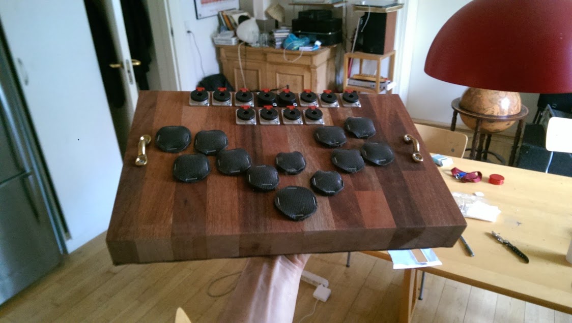
As you might be able to see in the photos, the piezo triggers are contact microphones, which are put in a sandwich of protective material with a bouncing effect (in order to give some mechanical feedback to your strokes).

There’s a ton of guides and talks on contact microphones. Here’s a link to a really easy and low tech version that’ll suffice. You might consider improving the construction details as you desire. Remember to keep the cable open, do not connect any plug in the other end of the cable.

We’ve been in various hardware stores and tried out different material for covering the contact microphones and our solution was a thin car floor mat with a rubber backside and synthetic short-haired fabric on the frontside. Cut the mat into round pieces. You will need 2 per piezo trigger, each with a diameter that is approximately 2cm longer than the diameter of the contact microphones. (Depending on the available space in your layout, you might be able to downsize the mat pieces.)

The two pieces of mat will be conjoined with the contact microphone in between and facing downward (i.e., the piezo crystal side pointing down and the brass side pointing up). To do this, first attach the bottom piece to the woodblock with a stapler. Make sure that the cable hole is within the perimeter of the bottom piece. Then, cut a hole through the bottom piece in order to lead the cable through. Then, stick the contact mic onto the bottom piece (use double-sided tape or the like). Make sure the cable can be lead through to the hole in the bottom piece and wood block effortlessly. Then place the top piece of the mat and carefully attach the two pieces together using a powerful stapler. Repeat this step with all the triggers.

IMAG1638

STEP 6: CONNECT THE TRIGGERS TO THE NEUTRIK PLUGS

Take the cable through the wooden block to its backside. Lead it according to your cable routing diagram from step 4. Leave approximately 5cm of surplus length on the backside for a later operation. Lead the cable through the Neutrik hole and solder it to the Neutrik plug. Test the connection with a signal test tool (multimeter). Screw the Neutrik plug onto the wood block.

STEP 7: FASTEN CABLES

With the stapler and some small protective pieces of car floor mat, attach the cables on the backside of the wooden block. Leave a section big enough to do a small soldering operation. Cut the cable in the middle of the surplus length and adjust the cables so it fits your cabling routes. Resolder the cables and protect the soldering with a piece of shrink tube, electrical tape or the like. Repeat with all the cables on the backside of the wooden block.

IMAG1656

STEP 8: ATTACHING BACKSIDE COVER

We used the same car floor mat for backside cover, facing the rubber side downwards to add some friction. Cut out a piece of car floor mat that fits the wood block and staple it meticulously around all the edges of the wooden block.

IMAG1674

STEP 9: ATTACH HANDLES

Make sure the handles don’t exceed the dimensions of the flight case when attached to the wooden block. We spent some time finding handles small enough since we didn’t consider this beforehand. A good tip is to visit a maritime equipment hardware store. Usually they have handles of all kinds and shapes since boats have tons of handles in different variations. Placing the hinges is a matter of space, aesthetics and of course, their practical functionality. So it’s up to you to find the sweet spot.

IMAG1671

Now you have a playable electronic drum set or basically any triggered instrument. All that is left for you to do now is to plug the Jack cables from your drum pad into the channel of your choice on your drum brain or to map your MIDI signals (if you are using DAWs like Logic, Ableton Live, or whatever sequencer to trigger your sounds).
Enjoy!

IMAG1675

IMAG1673