If you aspire to do more than blink an LED with your new Arduino or Netduino, you need a prototyping shield that allows you to build a circuit. After listening to our readers and customers, we created a new kind of prototyping shield that supports the needs of noobs as well as advanced users. Introducing MakerShield!

Unlike conventional prototyping shields, Maker Shield lets you create circuits the way you want, and easily change them without having to solder. All of the MakerShield’s major components and pins are user-assignable, allowing you to jump from any component header pin to any pin on the microcontroller. Make all the changes you want. Just jump and go!

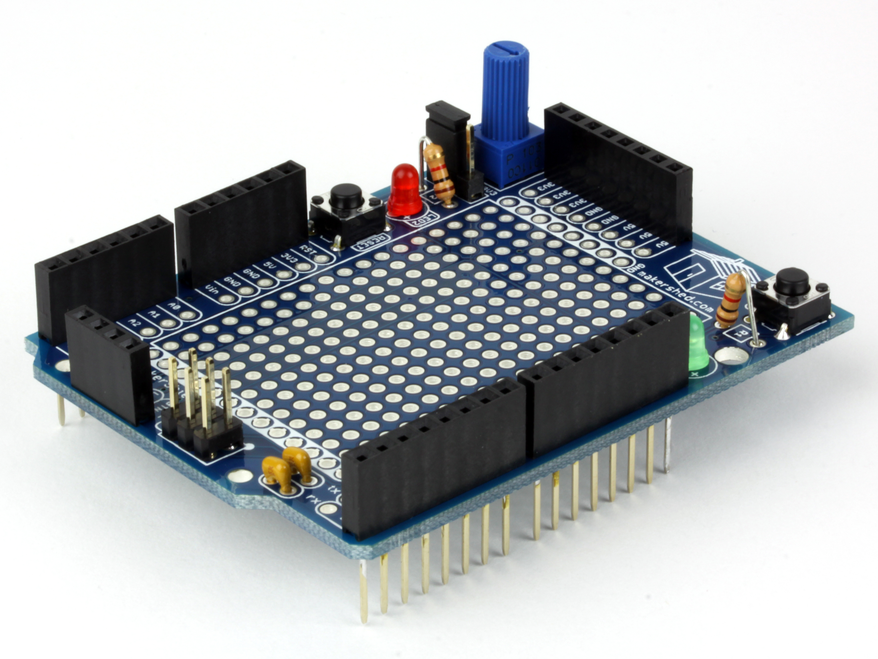
The MakerShield’s potentiometer lets you switch between 5V or 3.3V signals, so the growing numbers of Netduino users can use MakerShield too.

Being able to change the pins connected to the onboard LEDs, button, and potentiometer allows beginners to learn Arduino software with ease, while more advanced users will appreciate the convenience of the onboard components, the incredible flexibility, and the ability to stack another shield on top — the MakerShield uses stackable header pins and retains the original ICSP pin locations of the Arduino.

Project Steps

Compare the kit contents to those listed on the product page in the Maker Shed.

First we will add the red and green LEDs. The LEDs have 1 long lead and 1 short lead. The long lead goes into the hole labeled (+) on the PCB. We recommend putting the green LED on the right side (side with the logo) and the red on the left side, but choice is yours.

After you put the LEDs into the board, flip it over and bend the leads outwards so they will stay in place while you solder them.

After you solder the leads, clip them close to the board.

Next, add the matching resistor for each LED. They are inserted into the board at locations R1 and R2. Resistors are not polarized, so you can place them in either direction. Notice how the resistor is standing up, or “tombstoning.” This board is packed with components, and this is a great way to save space!

The second picture shows the resistor for LED2. It is soldered in the same way as LED1.

Next, we’ll add the buttons to the board. They snap in place at locations BTN1 and RESET (possibly BTN2). Flip the board over, solder the leads, and trim. Easy!

Now we will add the power filtering capacitors. They aren’t polarized, so their orientation doesn’t matter. Add them to the area of the PCB by the “tx” and “rx” pins. Make sure they match the silkscreen and are placed in the correct holes.

Next, bend the leads out, the same as you did with the LEDs and resistors, and solder them in place.

Adding the ICSP header. It’s much easier to add the ICSP header pins by placing them in the appropriate spot on the PCB (labeled ICSP) and flip the board over on a flat surface. This holds the pins against the board and makes soldering a snap.

Note: Be sure to trim the leads on the back. They need to be as flush as possible.

Solder the 3.3V – 5V jumper pins. Use the same method for soldering in the 5v – 3.3v 3-pin header. The short ends of the pins should be placed through the board and soldered. The long leads will be facing up, or on the topside of the board.

Next, go ahead and add the included jumper so you don’t lose it! This jumper allows you to select either a 3.3v signal from the potentiometer, or a 5v signal.

Adding the power and user selection header pins. Now we can add the 8-pin female header (with the short pins!) on the PCB at the top of the board.

Note: Be sure to use the 8-pin header with the short pins!

You can use a little piece of tape to hold the female header pins in place, or you can hold it with your finger and solder 1 pin to hold it in place. I wrap the solder around my PanaVise to keep it steady. Easy!

Use the same technique to solder in the 4-pin female header pin (with short pins!) to the location on the bottom of the PCB labeled “BTN1, LED1, LED2, POT1”.

Now it’s time to solder in the stacking header pins. Place the header pins in the PCB on the left and right side. You should have two 8-pin female headers on the right side and two 6-pin headers on the left. After you place them through the board from the front, carefully flip the board over on a flat surface and solder at least one pin of each header section.

In the second picture, you can see that each header has one pin soldered to the PCB. Now you can flip the board over and make sure all the stacking header pins are in alignment. Once they are aligned, go back and solder all the remaining pins. DO NOT TRIM THESE PINS!

The last step is to solder in the potentiometer. We solder this in last because it has a long shaft and would interfere with soldering in the female headers.

The potentiometer only fits one way. Orient it properly, bend the leads out a little, and solder in place. The last step is to trim the leads. You’re done!

Make sure the pins are all lined up and plug it into your favorite micro-controller. Now all you have to do is plan on what you’re going to make!