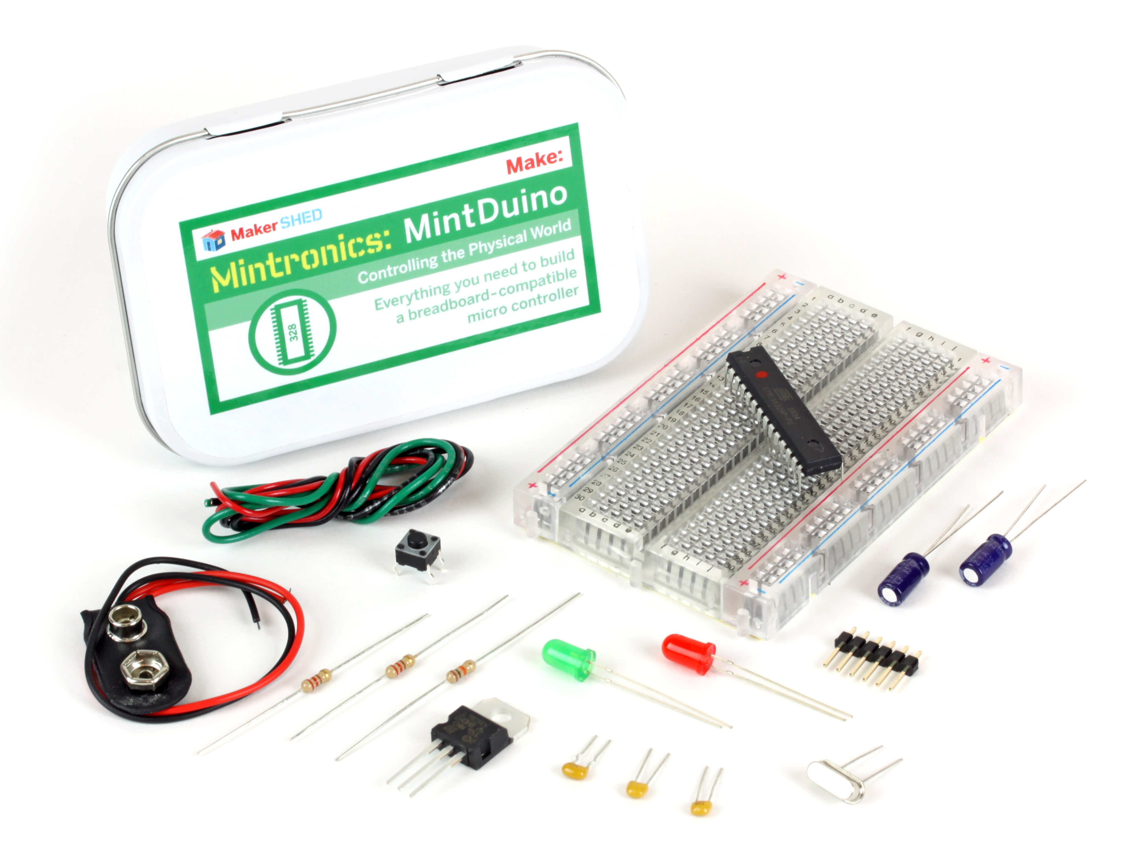
The MintDuino is perfect for anyone interested in learning (or teaching) the fundamentals of how microcontrollers work. It will have you building your own microcontroller from scratch on a breadboard, and then easily programming it from almost any computer via the Arduino programming environment.

Unlike pre-built microcontrollers, the MintDuino demonstrates the specific relationship between the wires, resistors, capacitors, and integrated circuits that enables you to program the microcontroller from your computer. After building the MintDuino, you’ll have a much better understanding of how microcontrollers work, and how electronics can interact with the physical world.

Project Steps

Start building your MintDuino by adding the 7805 power regulator. This converts the 9v power to 5v power that the ATMega can use.

Insert the 7805 into column “i” on the breadboard and rows 1,2 & 3 as pictured. The metal heatsink should be facing the right (or column “J”)

Now we are going to add one 10 uF capacitor to the power regulator.

I like to trim the leads down so it doesn’t stick so far out of the breadboard. One lead is longer than the other. The long lead is the (+) lead and the short one is the (-) lead. If you trim it, make sure to keep the lengths different lengths so it’s easy to identify the (+) and (-) leads.

Insert the (+) lead into “g1” & the negative lead into “g2”. Easy!

Next is the other 10 uF capacitor that we use to smooth out the power on the breadboard.

Insert the (-) lead into row 1 of the (-) power rail of the breadboard.

Insert the (+) lead into row 1 of the (+) rail of the breadboard as pictured.

Now let’s get some regulated power over to the power rails of the breadboard.

Start by stripping the ends of one piece of red wire cut to approximately 1/2″ long. Insert the wire from the (+) rail of the breadboard to “j3” of the breadboard.

Next strip the ends of one piece of black wire cut to approximately 1/2″ long. Insert the wire from the (-) rail of the breadboard to “j2” of the breadboard as pictured.

Now we are going to add the power LED (Red).

Start by cutting down the leads, as we did on the capacitor. Make sure to keep the long one (+), long, and the short one (-), short!

Now you can insert the red LED into the breadboard.

The longer lead (+) goes into “d2” and the negative (-) goes into “d1”

Let’s get the power distributed around the board and to the LED.

Start by cutting one red wire, approximately 1/2″ long and one black wire, approximately 1/2″ long. Strip both ends of each wire.

Insert the red wire from “f1” to “e4”, and the black wire from “f2” to “e5”.

Cut another piece of black wire about 1/2″ long (I’m going to stop saying “strip each end” each time) and insert it from the (-) rail of the breadboard (picture 2) and “b1”

While we are here, lets add a 220Ω resistor (red, red, brown) from the (+) rail of the breadboard to “b2”.

Lastly, cut one piece each of red and black wire about 1 1/2″ long and connect the right side rails together. Remember to connect (+) to (+) and (-) to (-) as in picture 3.

Power it up!

Now connect the battery clip’s red wire (+) to “d4” and the black wire (-) to “d5”.

Connect a 9v battery and the red LED should light up.

If not, immediately unplug the power and double check everything!!!

Now you have a nice 5V regulated power supply from a 9V battery. Your ATMega will thank you for it!

OK, enough fun. Unplug the battery and let’s get started with the micro controller.

Now it’s time to hook up the ATMega 328.

Did you unplug the battery? Yes? Good! Let’s get started.

The ATMega has a small “U”-shaped notch on one end. This notch lets you know where pin 1 is on the integrated circuit (IC) or “chip”. If you hold the chip vertically, with the notch on top, pin 1 is directly to the left of this notch.

Insert the IC so the notch is towards the power supply we already built.

Insert pin 1 into “e9” as pictured.

You may need to bend the pins in a little bit so they don’t flare out too much. You shouldn’t need a lot of force to insert the IC.

Time to add the crystal.

The crystal is inserted into the breadboard at “b17” & “b18”. Orientation isn’t important; either way is fine.

The crystal needs some capacitors to work properly. The two 22pF capacitors are not polarized, so orientation does not matter.

Use one 22 pF capacitor (marked 220) and insert it into the the ground rail of the breadboard and “a17”.

The other 22 pF capacitor (marked 220) is inserted into the the ground rail of the breadboard and “a18”.

While we are here, cut a 1/2″ piece of black wire and connect the ground rail of the breadboard to “a16”.

Time for more power!

Cut 3 pieces of red wire, all of them about 1/2″ in length, and one black wire 1/2″ in length.

Use one red wire to connect the (+) rail of the breadboard to “j16”

Use another piece of red wire to connect the (+) rail of the breadboard to “j17”

Use one black wire to connect the (-) rail of the breadboard to “j15”

Back to the other side of the board (by the crystal). Connect the remaining red wire from the (+) rail to “a15”.

Now let’s wire up a status LED. This will help us know everything is working properly.

You can trim the LEDs leads if you prefer; also cut one piece or red wire about 3/4″ long.

Insert the longer lead of the LED (+) into “i24” and the shorter lead (-) into “i25”.

Next connect the (-) ground rail of the breadboard to “j25” using a 220Ω resistor (red, red, brown).

Last but not least, connect the “h24” to “h18” with the red wire as in picture 3.

Now you have an LED connected to “pin 13” of the “Arduino”. It’s actually not pin 13 of the ATMega. The Arduino IDE uses different definitions for the pins to simplify its use. I’ll go over the pins in the last step of the build.

Time for another test.

Go ahead and reconnect the battery (see step 7).

The red power LED should light up immediately, followed by the green LED. The green LED will blink. This is because a simple blink program has already been uploaded to the ATMega.

If the LEDs don’t light up, immediately disconnect the power, and check all you connections again.

But how do you program it? That’s next!

Adding the reset button.

Cut one piece of black wire about 1″ in length.

Connect the ground rail (-) of the breadboard to “d6”.

Cut another piece of black wire about 1/2″ in lenght and connect it from “d8” to pin “1” of the ATMega at “c9”

Now press the button into the breadboard. It only fits 1 way, so make sure the pins all line up properly. The four leads of the button will fit in “e6”, “e8” & “f6” & “f8”.

The last step is to connect “b9” to the (+) rail of the breadboard with a 10kΩ resistor (brown, black, orange).

Wiring the programming pins.

Start by using a pair of pliers to adjust the pins (gently) to be centered in the plastic rail.

In picture 2, you can see the 3 pins on the right are perfect. The 3 pins on the left still need to move down a bit.

By centering the pins it makes it much easier to plug in the FTDI adapter later.

Once they are centered, insert the 6 pins in column “b” from “b25 – b30” as pictured.

Now we need to wire up the programming pins.

Cut three lengths of green wire (color may vary) approximately 2″ each.

Use one wire to connect “d10″ to e27”

Use one wire to connect “c11” to “d26”.

Use one green wire to connect “d9” to “c23”

It’s a little hard to see. Make sure to double check all the wires.

Next, add the 100nF capacitor (marked 104 on one side and K1K on the other) from “c25″ to b23”. It is not polarized, so inserted either way is fine.

The final step is to add a 1/2″ piece of black wire from “a30” to the ground rail (-) of the breadboard.

All done! Now you can start programming the ATMega!

To program your new MintDuino you need a USB -> serial connection.

We suggest you use an FTDI Friend, but most FTDI cables will work.

The FTDI friend can be purchased at the Maker Shed.

Does anyone else think it looks like a scorpion?

Here are some labels to show you the ATMega pins (left) and the “Arduino” pins (right).