YouTube player

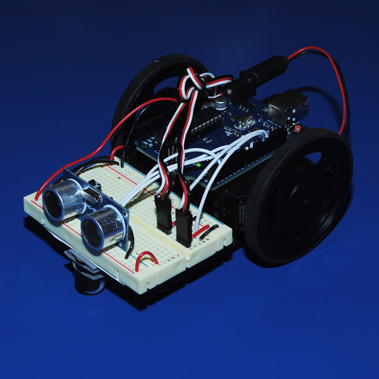
This guide shows you how to quickly and easily build an Arduino robot. Robotics is an exciting and fun hobby that has become very affordable in recent years. What would have required a lot of money and experience to do a few decades ago is now affordable, easy, and most of all, FUN!

Not sure if Arduino is right for you? Make:’s interactive Board Guide lets you dial into the field to find the best board for your needs.

Simple Arduino Robot

The parts used in this guide can all be purchased together in the Funduino UNO Robotics Kit, but you can follow along with a different kit just as easily as long as you have similar components.

Keep in mind that this tutorial shows just one way to make a robot — you’re limited only by your budget and imagination. If you want to buy more sensors, or a nicer chassis, go for it! The entire process may take an hour or two, so get ready to have some fun!

What will the next generation of Make: look like? We’re inviting you to shape the future by investing in Make:. By becoming an investor, you help decide what’s next. The future of Make: is in your hands. Learn More.

Project Steps

Making the Chassis

Place the battery pack face down and orient it so that its cable is facing you.

Take two pieces of double sided tape and adhere them on the long sides of each servo. Ensure servo alignment at the bottom.

Peel the backing off the tape and firmly press the servos onto the battery pack.

Note:

Make sure to apply the servos on the end where the wire is coming out, oriented so that the shafts are towards the end of the battery pack.

Note: Ensure that the servos are pressed firmly together and that they are centered on the battery pack.

The easiest way to do this is to peel the back off the tape, hold one servo in each hand while pressing the backs of them against each other, and then pressing them down onto the battery pack at the same time.

Breadboard & Arduino

Attach the breadboard to the top of the battery pack. You can peal the backing off the adhesive foam-tape already on the breadboard, or you can use your own double-sided tape –I recommend the latter.

The Arduino will ride atop the servos in this robot design. Cut a piece of tape slightly less than the width of the Arduino and place the tape on the servos.

Peel the backing off the double-sided tape and press the Arduino onto the tape.

Note: Avoid overhanging the Arduino above the breadboard too much.

Wheels & Caster

Take the wheels and firmly press them onto the servos. The wheels fit very tightly, so it takes a lot of force to get them on!

The last step in the assembly process is putting a caster on the front of the robot. As you can see in the picture, the caster is about 1/4″ too short, so we need to find something to put between it and the breadboard.

Using scrap wood and tape, build up a spacer to increase the clearance of the caster. Once the spacer is the correct size, use double-sided tape and secure the breadboard to the spacer, and the spacer to the caster.

Wiring the Servos

Cut two 3-pin segments off of the long break away header.

The header pins’ black plastic piece may have shifted off-center. Using pliers, carefully reposition the black plastic piece so it’s at the midpoint of the metal pin.

Press the headers into the breadboard, then attach the servo cables into the headers, with the black wire on the cables on the left-hand side.

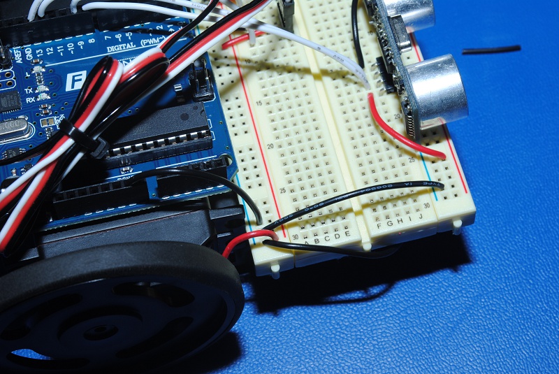
Connect the red wires on the servos to the breadboard’s positive (red) rail, the black wires to the GND (blue) rail, and the white wires to pins 12 and 13 on the Arduino.

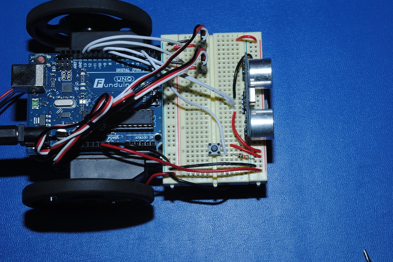
Note: Keep your circuit layout tidy by using the power and ground rails of the breadboard closest to the Arduino (see image three).

Adding a Sensor

Insert the ultrasonic sensor so it’s facing towards the front of the robot, and overhanging the unused power and ground rails.

Note: The sensor is not plugged into a power or ground rails, it’s in the body of the breadboard.

Also, zip-ties help to keep your robot’s cabling tidy.

Connect the ultrasonic sensor so that it’s VCC pin is wired to front power (red) rail on the breadboard (not the back one!).

Connect a black wire to the GND pin of the sensor and to the GND (blue) power rail.

Finally, connect a white wire to the Trig and Echo to pins 8 and 9 on the Arduino, respectively.

Connecting the Power (pt. 1)

The servos shouldn’t be powered through the 5V pin on the Arduino because they can draw more current then the Arduino can provide. The correct way is to power the servos is directly from a battery pack (either the same battery pack powering the Arduino or, even better, a separate battery pack).

Four AA batteries will supply the motors with somewhere between 4.8V and 6V depending on the battery type, which what our servos need. The easiest way I’ve found to do this is to stick a red wire into the second spring from the left and a black wire into the last spring on the right in the battery pack.

Note: Pay close attention to the orientation of the battery pack in the above picture. Make sure when you put the red wire into the “second spring from the left” that the battery pack cable is on the bottom left. If you have a multimeter, this would be a great time to use it to verify you’re plugging in the wires to the right places.

Connecting the Power (pt. 2)

Run the red and black wires we just put in the battery pack springs to the power rails at the back of the breadboard (the one the servos are plugged into).

Use a black wire to connect the GND pin on the Arduino to the GND rail at the back of the breadboard, then use another one to connect the two GND rails on the breadboard together (do not connect the positive rails together!).

Now, take a red wire and connect the 5V pin on the Arduino to the FRONT power (red) rail on the breadboard (not the back power rail!).

Adding a Kill Switch

Finally add a kill switch to the robot so that it can be stop it without having to unplug the power.

Take a push button switch and put it across the gap in the breadboard. Then use a red wire to connect one side of the switch to the front power rail, a 10kΩ resistor to connect the other side of the switch to GND, and a white wire to connect the side of the switch with the resistor to pin 2 on the Arduino.

Programming your Robot

Now that the robot is finished, you’ll want to program it’s behavior.

Check out the code for this robot and my

tutorial for how you can write your own sketches.