


Charlieplexing is an ingenius method for controlling many LEDs without using many microcontroller pins. You can turn on or off one LED at a time. To light more than one LED at a time, you can scan the LEDs by turning a sequence of them on and off really fast. The number of LEDs you can control is determined by this formula: N pins * (N pins – 1). For example, if you have 4 pins, you can control 12 LEDs (4 pins * 3 pins). If you have 2 pins, you can control two LEDs, which makes it a little silly to employ Charlieplexing, since you could simply connect each LED to an MCU pin and then to ground. Charlieplexing makes more sense for more than two LEDs. Nine pins will get you 72 LEDs!
Here is an ATmega328 on a custom PCB controlling 20 LEDs (the 21st is on its own pins) with just 5 pins:

Charlieplexing takes advantage of the fact that LEDs are diodes: Current flows in only one direction through an LED. Connect two LEDs in parallel with each but with opposite polarity so that only one conducts (lights up) at a time and that is the basis of Charlieplexing.
The ATmega328 pins can source upwards of 40 mA. The grand total of current from Vcc to GND in an ATmega328, however, is capped at 200 mA. Keep that in mind when pumping electrons through your Arduino or ATmega328. In this project, we’ll only ever have a single LED turned on at a time, so no more than roughly 20 mA will be running through the microcontroller’s pins at any time (not including what the MCU takes itself, of course).
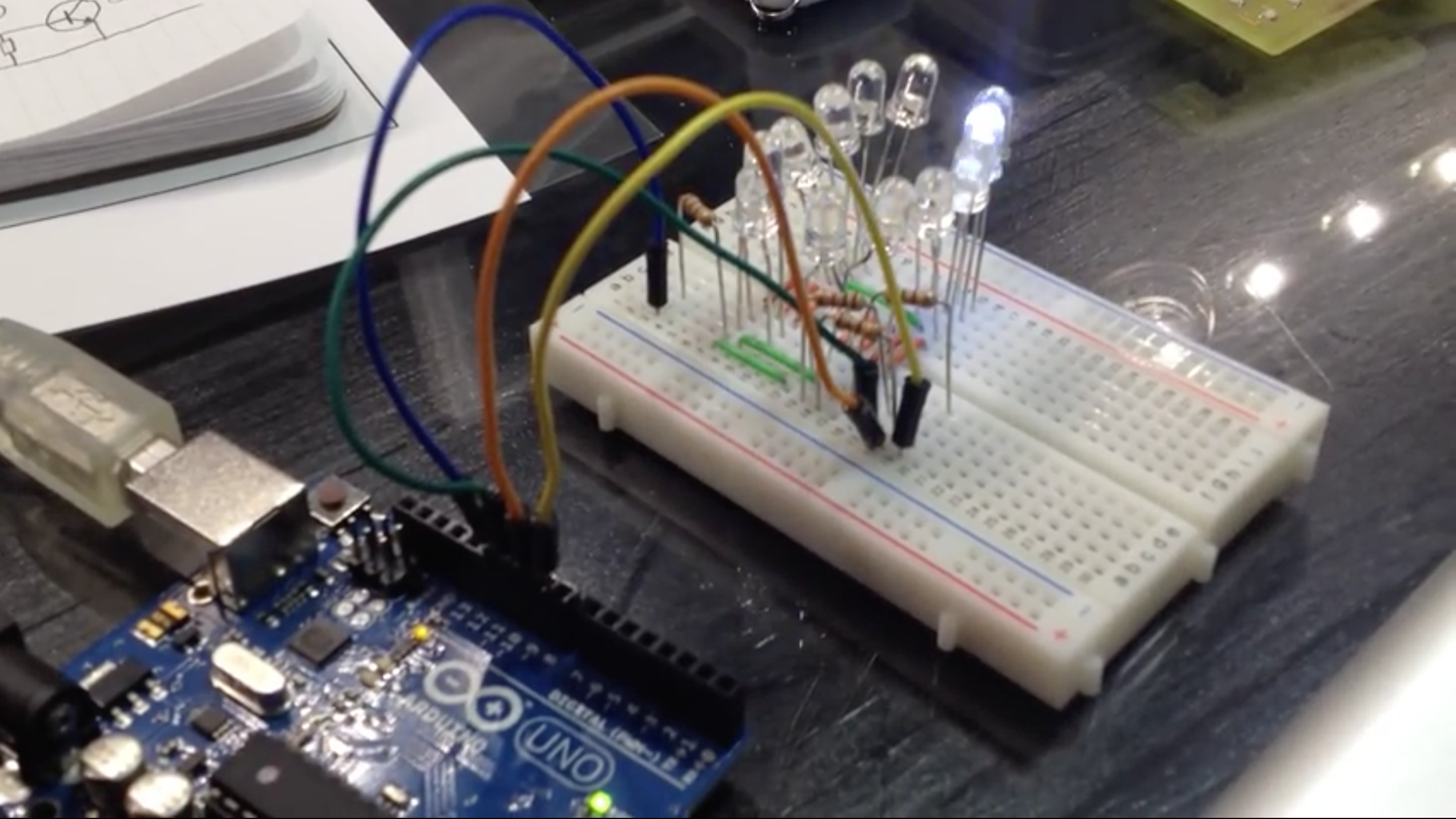
In this project, we’ll set up a simple Charlieplexing circuit with 12 LEDs controlled by an Arduino that will look like this:

I’ll walk you through connecting 12 LEDs to four pins on your Arduino. The Arduino sketch will make the LEDs “chase” in a circle(ish). The breadboard set up for this gets nuttier and nuttier the more LEDs and pins you add. I’m going to stop at four pins, mostly because the breadboard starts to look crazy and four pins will get you going on your own quite easily.
I wrote the Arduino code to make it easy to add or remove LEDs. There is a simple function to call to turn on any given LED. You can nab the Arduino code for this project right here:
This file contains bidirectional Unicode text that may be interpreted or compiled differently than what appears below. To review, open the file in an editor that reveals hidden Unicode characters.
Learn more about bidirectional Unicode characters
| #define A 12 | |
| #define B 11 | |
| #define C 10 | |
| #define D 9 | |
| #define PIN_CONFIG 0 | |
| #define PIN_STATE 1 | |
| #define LED_COUNT 12 | |
| int matrix[LED_COUNT][2][4] = { | |
| // PIN_CONFIG PIN_STATE | |
| // A B C D A B C D | |
| { { OUTPUT, OUTPUT, INPUT, INPUT }, { HIGH, LOW, LOW, LOW } }, // AB 0 | |
| { { OUTPUT, OUTPUT, INPUT, INPUT }, { LOW, HIGH, LOW, LOW } }, // BA 1 | |
| { { INPUT, OUTPUT, OUTPUT, INPUT }, { LOW, HIGH, LOW, LOW } }, // BC 2 | |
| { { INPUT, OUTPUT, OUTPUT, INPUT }, { LOW, LOW, HIGH, LOW } }, // CB 3 | |
| { { OUTPUT, INPUT, OUTPUT, INPUT }, { HIGH, LOW, LOW, LOW } }, // AC 4 | |
| { { OUTPUT, INPUT, OUTPUT, INPUT }, { LOW, LOW, HIGH, LOW } }, // CA 5 | |
| { { OUTPUT, INPUT, INPUT, OUTPUT }, { HIGH, LOW, LOW, LOW } }, // AD 6 | |
| { { OUTPUT, INPUT, INPUT, OUTPUT }, { LOW, LOW, LOW, HIGH } }, // DA 7 | |
| { { INPUT, OUTPUT, INPUT, OUTPUT }, { LOW, HIGH, LOW, LOW } }, // BD 8 | |
| { { INPUT, OUTPUT, INPUT, OUTPUT }, { LOW, LOW, LOW, HIGH } }, // DB 9 | |
| { { INPUT, INPUT, OUTPUT, OUTPUT }, { LOW, LOW, HIGH, LOW } }, // CD 10 | |
| { { INPUT, INPUT, OUTPUT, OUTPUT }, { LOW, LOW, LOW, HIGH } } // DC 11 | |
| }; | |
| void turnOn( int led ) { | |
| pinMode( A, matrix[led][PIN_CONFIG][0] ); | |
| pinMode( B, matrix[led][PIN_CONFIG][1] ); | |
| pinMode( C, matrix[led][PIN_CONFIG][2] ); | |
| pinMode( D, matrix[led][PIN_CONFIG][3] ); | |
| digitalWrite( A, matrix[led][PIN_STATE][0] ); | |
| digitalWrite( B, matrix[led][PIN_STATE][1] ); | |
| digitalWrite( C, matrix[led][PIN_STATE][2] ); | |
| digitalWrite( D, matrix[led][PIN_STATE][3] ); | |
| } | |
| void setup() {} | |
| void loop() { | |
| for( int l = 0; l < LED_COUNT; l++ ) { | |
| turnOn( l ); | |
| delay( 1000 / LED_COUNT ); | |
| } | |
| } |
On a side note, the Arduino digitalWrite() and maybe even the pinMode() calls are heavyweights compared to the standard AVR C register macros for directly manipulating bits in the DDRx and PORTx registers of the ATmega328 (or any AVR chip, for that matter). The Arduino calls gobble up a quite a lot of clock cycles when you call them, whereas the DDRx and PORTx macros translate to one or maybe two assembly instructions (WAY faster). When it comes to scanning over the LEDs rapidly to make more than one at a time appear to be on, the fewer clock cycles in between each LED during each refresh (or, “frame” of animation), the brighter and less flickery the LEDs will appear to be. The optimum way to scan these LEDs, especially when there are many of them, is to use direct register manipulation calls, NOT digitalWrite() or pinMode(). There is a great replacement for the Arduino calls out on Google Code that provides digitalWriteFast() and others to help speed up those common calls. Here is a link to the Google Code page for that library.
On a side note to the above side note… Here is a gist showing code that directly manipulates the DDRx and PORTx registers to save on cycles when switching between LEDs:
This file contains bidirectional Unicode text that may be interpreted or compiled differently than what appears below. To review, open the file in an editor that reveals hidden Unicode characters.
Learn more about bidirectional Unicode characters
| #define A 12 | |
| #define B 11 | |
| #define C 10 | |
| #define D 9 | |
| #define LED_COUNT 12 | |
| #define DDR_BYTE 0 | |
| #define PORT_BYTE 1 | |
| byte matrix[LED_COUNT][2] = { | |
| // DDR_BYTE PORT_BYTE | |
| // ABCD ABCD | |
| { 0b00011000, 0b00010000 }, // AB 0 | |
| { 0b00011000, 0b00001000 }, // BA 1 | |
| { 0b00001100, 0b00001000 }, // BC 2 | |
| { 0b00001100, 0b00000100 }, // CB 3 | |
| { 0b00010100, 0b00010000 }, // AC 4 | |
| { 0b00010100, 0b00000100 }, // CA 5 | |
| { 0b00010010, 0b00010000 }, // AD 6 | |
| { 0b00010010, 0b00000010 }, // DA 7 | |
| { 0b00001010, 0b00001000 }, // BD 8 | |
| { 0b00001010, 0b00000010 }, // DB 9 | |
| { 0b00000110, 0b00000100 }, // CD 10 | |
| { 0b00000110, 0b00000010 } // DC 11 | |
| }; | |
| void turnOn( byte led ) { | |
| DDRB = matrix[led][DDR_BYTE]; | |
| PORTB = matrix[led][PORT_BYTE]; | |
| } | |
| void setup() {} | |
| void loop() { | |
| for( byte l = 0; l < LED_COUNT; l++ ) { | |
| turnOn( l ); | |
| delay( 10 ); | |
| } | |
| } |
This project will assume you know how a breadboard works, how to calculate the proper current limiting resistance for an LED running on 5 volts and what the cathode (ground/negative) and anode (positive) leads are on your LEDs.
Related articles
- Charlieplexing LEDs with an AVR ATmega328 (Arduino) (adafruit.com)


