

I wanted to have the movie’s theme song play along with flashing lights every time a trick-or-treater opened the gate to my front yard this October.


The MSGEQ7 is an audio frequency analyzing chip that’s often used for graphical displays. When used together with three MOSFETs it’s perfect for driving RGB lighting strips. The challenge then became how to trigger the music to play back. I found out that it was possible with an Arduino — you just add a shield with a memory card slot. As I was ordering one online, a sidebar advertisement beckoned me toward a product perfectly suited toward my purposes.
Adafruit sells a Mini Audio FX Board that makes triggering playback of a WAV or OGG audio file incredibly simple. The board operates on anything from 3V–5.5V and the output pins can be connected directly to headphones or to an amplifier. It has a USB port which, when plugged into a PC, acts as a 16MB flash drive onto which the audio files are saved. If you use the compressed OGG file format, you get something in the neighborhood of 16 minutes of playback.
There’s no programming needed at all — it’s already built into the board. There are eight different trigger pins and the filenames need to be in a format that relates to one of the pins. Each pin can produce five different playback modes, again depending on the format of the filename. All that’s needed is to ground out the selected pin. There’s also a reset pin to stop playback and wait for the next trigger.
To trigger the board, I’m using an ordinary magnetic door switch, a type normally used for security systems. It’s important that the contacts close when the magnet is removed. I’m mounting it on the fence with some brackets that I designed with Openscad and made with my Robo3D printer. If you don’t have access to a printer yourself I’m sure you could make something that works with duct tape and some kind of a spacer.


I have an audio jack and a splitter connected to the output pins so I can route the audio to my Berlin Boombox (another Kickstarter reward) and to the input of the MSGEQ7+MOSFET board. This sample sketch on GitHub includes the required pin connections to an Arduino board. The connections for the RGB strips are marked on the board as well as the connections for the power to drive the strips.
The MSGEQ7 reports back to the Arduino, giving the volume level of seven different frequency bands, but only three are used via the Arduino’s PWM outputs for each color LED. Although my programming skills are limited, I was able to figure out how to use three more frequencies to control the three remaining PWM outputs, which allows a second strip of LEDs to be connected. The eBay seller has another board, with three MOSFETs only, to power the second strip.
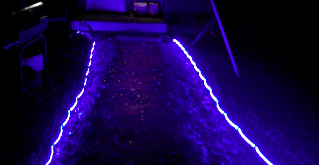
The final challenge was to come up with some way to arrange the flexible RGB strips along the sidewalk leading up to my front door. I didn’t want to lay them on the ground so I bought some short Victorian-style border fencing from Amazon, similar to what you might see bordering a small garden.
I ran it down either side of the porch out toward the fence and laced the RGB strips in and out as far as five meters would go. I also ran some 18-gauge speaker wire along the bottom all the way out to the gate for the magnetic switch. It’s been raining a lot lately so I wrapped up the switch with electrical tape to keep it dry.

To extend the LED wiring into the house I used some 4-conductor 22-gauge cables, which are just the right size to plug into the connectors on the RGB strips. More electrical tape here keeps them dry and prevents them from pulling out.
The boards are sitting on a stool just inside the window. I’m using a 4xAAA battery pack to power the Arduino. The Mini Audio FX board gets its power from the Arduino’s 5V pin. The 12 volts required by the LEDs are provided by a wall wart connected to the two MOSFET boards with a connector I bought at a local electronics store.
This is gonna be great. Bring on the trick-or-treaters!


