w_dsc8317_nologo


Take your cup of Joe from classic to classified with a tilt-triggered spy camera.

The trick is to modify two paper coffee cups — install the device in one, slide it into the second, and align holes cut in the bottoms of each. Two LEDs can be seen through the standard plastic lid — one illuminates when the tilt switch is activated, the other flashes twice after a picture has been taken.

Think your cover has been blown? Simply rotate the cups to hide the camera.

This project combines several modules into a tilt-triggered spy camera that fits inside a coffee cup. The component which triggers the tilt is the Memsic 2125 accelerometer, a dime-sized component which you can see here:

memsic2125_pic

"The Memsic 2125 is a low-cost thermal accelerometer capable of measuring tilt, collision, static and dynamic acceleration, rotation, and vibration with a range of ±3 g on two axes. Memsic provides the 2125 IC in a surface-mount format. Parallax mounts the circuit on a tiny PCB providing all I/O connections so it can easily be inserted on a breadboard or through-hole prototype area."
“The Memsic 2125 is a low-cost thermal accelerometer capable of measuring tilt, collision, static and dynamic acceleration, rotation, and vibration with a range of ±3 g on two axes. Memsic provides the 2125 IC in a surface-mount format. Parallax mounts the circuit on a tiny PCB providing all I/O connections so it can easily be inserted on a breadboard or through-hole prototype area.”

You can read more on the component’s specifications on its datasheet, and a get basic understanding of the accelerometer’s interaction with the Arduino using the pulseIn() function here.

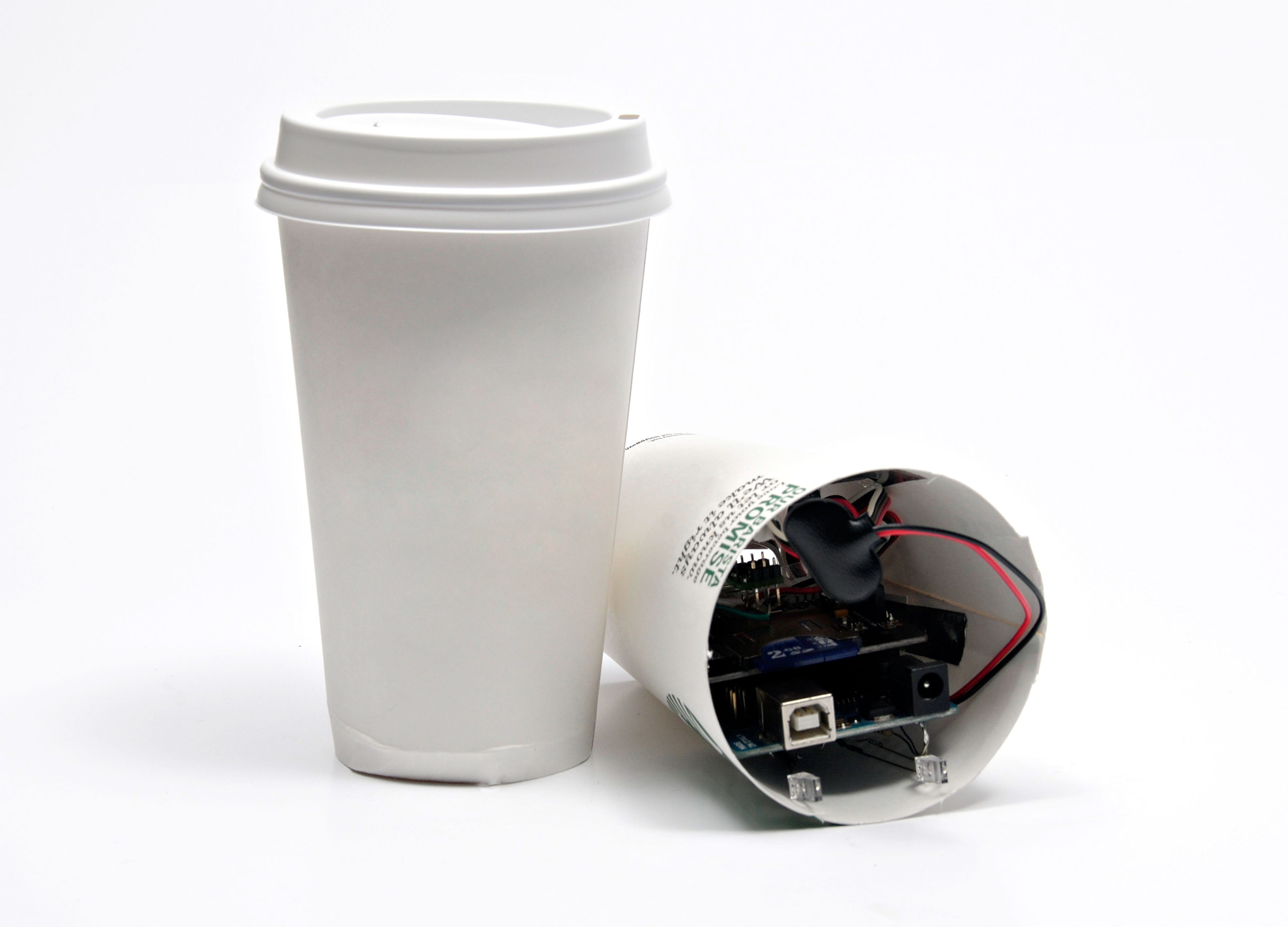
The project is installed in one paper cup with some modifications to it: the top is trimmed off, and a hole is cut in the bottom for the camera’s lens to point out. This cup will then slip in to the other cup, which also has a hole cut in its bottom. With the two holes lined up, when you lift and tilt the coffee cup the LEDs will illuminate: one will turn on when the tilt switch is activated, and the other will flash twice after a picture has been taken. You can see the light from the LEDs through the plastic lid.

Depending on the model of TTL Serial camera you acquire, you will need to experiment with how to mount the camera inside the cup. Larger form factor cameras will likely not be able to point directly out the bottom of the cup, and instead the image will need to be ‘bounced’ using a reflective mirror tile. I have provided detailed shots below on how to make this happen. However smaller form factor cameras (whose PCB is smaller and which contain through-hole connections instead of extending leads) should be able to be installed in such a way that the lens points directly out of the cup’s spy hole. Keep in mind you need room for the Arduino and SD card shield, and other components.

Experiment with the TTL Serial camera you acquire, grab some additional paper coffee cups, and play around with how to install your camera. In the steps and images below I have used quite a large spy hole, to guarantee the lens sees enough light and therefore captures a quality image. You may want to decrease the size of the spy hole, given the diameter of your camera’s lens, and the size of cup/s you are using to contain the project.

In other words, have fun customizing your Coffee Cup Spy Cam!

Project Steps

Gather The Parts

At the heart of this project is the Arduino Uno Rev 3. And yes, this will all fit inside a large coffee cup!

Originally I tried this with the Arduino Micro, but the emulated serial port on that board made it difficult to communicate with the camera module, so I would avoid this for now.

You’ll also need a TTL serial JPEG camera module, a SD card shield, and the Memsic 2125 2-axis accelerometer, and other various components such as resistors and LEDs. Some parts listed above are purely for testing, so read through the project first to determine what you already have on hand and what you need to assemble the project.

Focus the Camera

Depending on the JPEG camera module you use, the lens assembly will likely be tight out of box, and only able to take blurry pictures. Wire up an RCA connector to the video output and hook it up to a TV. You’ll have to loosen up the lens quite a bit before the image comes into focus. Once a visible image is acquired, put some adhesive tape around the lens to keep it in position (it’s fairly easy to knock it back out of focus when handling the module).

Note: If you don’t have a TV/monitor with RCA input, connect the JPEG module as you normally would to an Arduino with SD card shield. Then, initiate the camera to take photos to the SD card, inspecting the photos after each shot, and slowly adjusting the focus of the lens. This will take time, but requires no additional tech.

Test the SD Card

Pictured is version 3 of the Seeed SD card shield. Depending on availability in your area, the version 4 shield may be in stock. Regardless of the version number, follow the instructions here for formatting your SD card and testing the shield.

The biggest challenge with using an SD card with an Arduino is finding one small enough, and getting the right format. I used a 2Gb (increasingly rare) SD card and formatted this on a PC to the FAT (not FAT32) file system. I have found that any other configuration (8Gb, 16Gb, etc.) is beyond the capabilities of the Arduino library. If you find that the card is not saving files, or if they are 0 bytes, it is likely that the library is not communicating correctly. Keep reformatting the card till you start to see proper files created.

Note: The pin for SS or “chip select” on the shield I am using (v3.0) is pin 10; with v4 of this shield it will be pin 4. It may be different for other shields. In the next step when uploading the software to the Arduino, be sure to note your shield’s “chip select” and edit the software accordingly.

Breadboard the Circuit

Depending on the JPEG camera module you use, you will want to have its library on hand.

While testing the code I put everything on a breadboard. I used rubber bands to hold all the components in place. The connections are fairly straightforward: the SD shield provides everything you need to hook up the SD card; the camera module needs +5V, GND, and serial in/out; the accelerometer output is connected to pins 2 and 3 of the Arduino.

At this point I added a couple of indicator LEDs on pins 6 and 7. These are connected with 220 ohm resistors. One LED will turn on when the tilt switch is activated, while the other will flash twice when a picture has been taken.

Wire the Accelerometer

With everything tested and confirmed to be working, it’s time to make permanent many of the component connections, and assemble everything into the coffee cup.

The Memsic 2125 is a two-axis accelerometer — perfect for what we need. The datasheet is available here. It’s actually quite interesting how it works: it measures the heat profile of a central element, suspended in a thermally conductive gas, on all four sides. When natural convection makes one side hotter than the other it determines that this side must be “higher” than the other. I wouldn’t have thought of that. :)

Cut and strip a few lengths of wire. I’m using four different colors to distinguish their function.

Wiring up the accelerometer is simple. In the third image above I have connected the black wire to GND, the green wire (Y axis) to digital pin 3, and the white wire (X axis) to digital pin 2. I used 22 gauge solid wire, as this connects to the SD shield header pins perfectly.

Since the camera module will be using the +5V, connect the accelerometer’s power line to +3.3V. Or, if you are feeling brave, you can solder the red wire directly to the +5V shield pin, like I did. ;)

Prepare the Coffee Cups

Grab a couple of paper coffee cups. Trim the top off of one, and cut a “half moon” in the bottom of this cup (see second image). Your camera will eventually point out of this hole. You will slide this cup into the other cup.

In the full-size cup, cut a corresponding “half moon” in the bottom. This will allow you line up the holes when you want to tilt the cup to take a photo, and rotate the contents of the container cup to disguise the bottom if necessary, to blend (pun intended) in incognito.

Assemble Bounce Mirrors (optional, for larger cameras)

Smaller camera modules likely do not need to follow this step. You can simply point the lens directly out the spy cup’s hole.

If you’re using a larger camera module, and it won’t fit in the cup with the lens directly pointing out the hole, you will need to bounce the image using a small mirror attached to a hinge.

The mirrors are small mirror tiles available from most craft stores (Joanne Fabrics, Michael’s, etc.). A mirror-bounce image will result in an upside-down image, which can later be corrected in any image editing software.

Pictured is the hinge attached to a magnet. This proved finicky, and eventually I settled instead on using aluminum tape to mount the hinge to the interior of the cup. Aluminum tape sticks to just about everything!

Tip: If you find the hinge is too loose, you can hit the barrel with a hammer — lightly — a couple of times to create the friction needed to hold the mirror in place.

Arduino Hacking 101

Let’s be adventurous! Instead of using battery packs, or a separate shield to accommodate our components, let’s solder directly to the Arduino Uno!

The power & ground connections on the underside of the Uno board have a dollop of solder on them and will easily be jumped to. Solder a 9V battery snap connector as shown in the image above.

I wired in the two signal LEDs across the power supply ground — the long leg of the LED goes to the Arduino output and the short leg goes to the resistor, which in turn is connected to the Arduino power input ground terminal (see the second image above at full-size resolution for a better understanding of these connections).

Experiment with the Uno and the size of your spy cup, and then build a “shelf” to support the Arduino. I used paperboard and aluminum tape. This is one of those places where you should feel free to “over-engineer” the mounting system.

Assemble the Spy Cup

Now, I’m not going to lie to you, installing all this stuff inside an innocent looking coffee cup is … err… tricky, to say the least.

You should be able to see the indicator LEDs through the “host” cup lid, and this helps hide the true intentions of the camera.

Conclusion

It should be possible to reduce the size of the device further by using the Arduino Nano form factor. A board could be created to hold a microSD card, and the accelerometer could be made to dock quite neatly with this.

Additionally it should be possible to configure some of the parameters for image capture (such as compression settings) using an analog input on the Arduino, like using a potentiometer to give control of how large a file is saved to the SD card.

What other ideas do you have for shrinkifying this project, or modifying the code for your specific spy scenario? Share your hacks and mods in the comments below — I look forward to seeing what you invent!