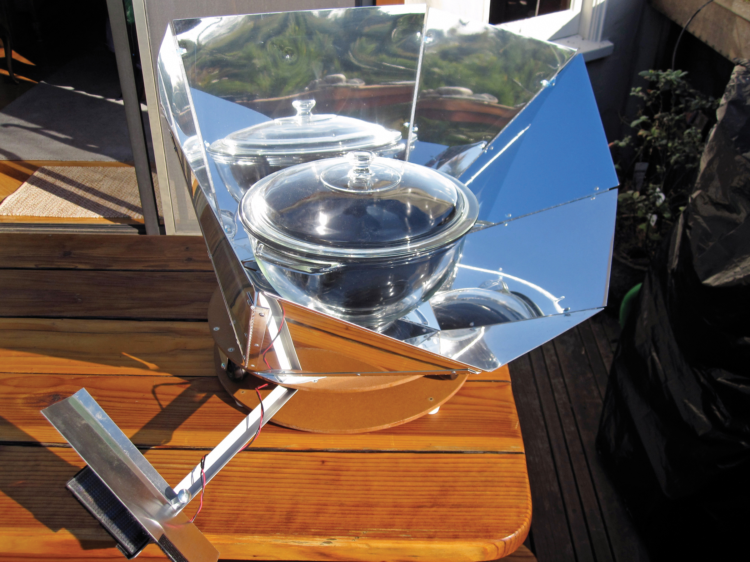
Once you’ve built your own Solar Tracking Platform, this tutorial will help you get started cooking some delicious sun-powered meals.

Keep in mind there are some differences between North and South:

Northern Hemisphere: the cooker faces south and the platform turns clockwise, tracking the sun east to west.

Southern Hemisphere: the cooker faces north and the platform turns counterclockwise, also tracking east to west.

By sundown, you have a delicious slow-cooked meal!

What will the next generation of Make: look like? We’re inviting you to shape the future by investing in Make:. By becoming an investor, you help decide what’s next. The future of Make: is in your hands. Learn More.

Project Steps

Make the turntable and base.

NOTE: This project is sized for my HotPot Simple Solar Cooker, with a footprint 11″ square and a reflector array that fans out 31″×26″ deep and 14″ high. You can modify the platform to fit other cookers, provided that the photocell, motor and wheels work together.

Cut the fiberboard into two 16″ squares, mark their centers, and then scribe a circle with a 7½” radius on each. Use a band saw or saber saw to cut just outside the circles, and sand them down to smooth 15″ circles.

Drill and countersink a ¼” hole in the center of one disk; this disk will be the turntable. Drill a 17/64″ hole centered in the other disk, the base.

Brush a polyurethane sealer over each disk, let dry, and add a second coat. Repeat on the other sides and around the edges.

Mark 4 quadrants on the base disk, drill pilot holes for the screws used to mount the feet, and install the feet. File down the tips of any screws that pierce the top surface of the base disk.

Gently sand the top surface of the base disk and apply a third coat of polyurethane.

Remove the axle from one of the wheels and bend both of its mounting flanges outward so that their tips are 1-13/32″ apart. This will be the drive wheel.

Clamp the 2″ round head screw in a vise, and file 2″-long flats on opposite sides of its tip.

Reassemble the drive wheel with the filed screw as its new axle and with the 2 jam nuts locking the wheel to the screw. Check that the wheel and axle turn freely.

Draw three 120° sectors on the underside of the turntable disk and use a wheel assembly to mark mounting holes for each wheel, spacing them equidistant around the perimeter. Center-punch and drill holes for the 12 mounting screws using a #21 bit.

At the drive wheel’s location, drill a fifth, 5/32″ hole centered between the 4 mounting holes. On the top of the turntable, draw a diameter line that passes through this 5/32″ hole. Countersink the 12 mounting holes, but not the 5/32″ hole.

Install the 3 wheels on the underside of the turntable, locating the modified drive wheel over the 5/32″ hole.

Make a photocopy of your protractor. Draw a line on the copy from the 90° mark down through the origin. If it has an inner set of numbers, white them out with correction fluid. Make a copy of the modified copy, and cut it into a neat wedge that includes the origin and the range of degrees from 60 to 120.

Paint the back of the protractor cut-out with polyurethane, then stick it to the topside of the turntable, with the origin centered over the 5/32″ hole and the 90° mark lined up with the diameter line from the steps in the 4th bullet point in Part II – Make the turntable and base. Apply more polyurethane over the paper as a sealer.

When the polyurethane is dry, run the 5/32″ drill bit through the protractor image’s origin point, so the 5/32″ brass tube can be mounted in this hole when needed.

Install the motor.

Cut ¾” lengths of both the ¼” aluminum and the 5/32″ brass tubing, to make 2 cylindrical shims. Clamp the aluminum shim in a vise and enlarge its inner diameter by drilling with a #21 bit. Check that the 2 shims nest together and will slip over the motor shaft and fit into the bronze bearing. Alternately, instead of the bronze bearing use a ¼” OD carriage bolt with a smooth shank 2.1” long. Cut off each end (head and threads). Drill (preferably with a drill press) a 5/32” hole the length of the shank. Drill a #21 hole half-way through

File a 1/8″-wide flat on one side of the bronze bearing, then center-punch marks on that flat, ¼” in from each end. Use a #21 bit to drill through the bearing at each mark, then use a #10-32 tap and handle to thread each hole for the setscrews.

Slip the bearing over the drive wheel’s axle, install 2 of the setscrews at the wheel end of the bearing, and make sure the wheel turns freely. Slip the nested shims over the motor’s drive shaft, then slip the shims and drive shaft into the other end of the bearing. Make a mark through one of the remaining setscrew holes with a fine-tipped marker, then use the narrow edge of a file to file slots through the shims that will permit the third setscrew to reach the flat on the motor’s drive shaft..

WARNING: Never apply torque to the motor’s shaft; you may strip its gears!

Use the #4-40 screw, nut, and washer to attach one mounting flange of the motor to the 1″×1″×½” corner brace. Fit together the drive wheel, coupling and motor shaft, keeping the motor’s flanges as horizontal as possible and the corner brace flush against the underside of the turntable. Mark and drill a #21 hole for the screw to anchor the corner brace; it will be off to one side from the drive coupling. Countersink the hole on the topside of the turntable and install a ½” flathead screw with a nut underneath to anchor the motor. Install the third setscrew to fix the bearing to the drive shaft.

With the turntable still inverted, lay the base disk on the wheels and check whether the motor’s unused mounting flange sticks up to touch the base disk. If so, file it down to open up some clearance.

Make the boom.

Cut a 14½” length of the aluminum angle and drill a ¼” hole 2¾” in from the right end, centered in the bottom leg of the “L.”

NOTE : These instructions are written for use in the Northern Hemisphere. If you’ll use your solar tracker in the Southern Hemisphere, you’ll need to translate the holes and cuts in this step to the opposite sides of the boom, so that the boom will extend from the left side of the turntable instead of the right. In either hemisphere, the boom extends to the west. You’ll also need to orient the PV cell so that it faces north instead of south, and reverse the motor wiring so that the turntable rotates counterclockwise.

Cut the 1½”-long ¼-20 round head screw down to 17″ and mount it tightly in the coupling nut.

Select one of the 3½” screws as a “sacrificial” screw. Mount a 7/32″-thick ¼-20 nut near its end, clamp the nut in a vise, and cut off one face of the nut right up to the threads on the screw.

Thread the coupling nut and screw through the back of the hole in the aluminum angle and screw your modified nut down onto the inside face, making sure this nut’s cut-off side is facing the right end of the boom.

Mix some metal epoxy and apply it generously between the nut and the inside of the boom, gluing the nut down so that its cut side faces the right end of the boom. After the epoxy cures, use a Dremel tool to grind the nut down flush with the edges of the angle, so the boom can be stored flat against the turntable.

Again at the right end of the aluminum angle, cut out a 3/8″-wide notch, 1 1/8″ to 1 1/2″ in from the end and on the opposite leg of the angle from the epoxied nut. On the left end of the notched leg, make a 3/8″-deep cut and bend the resulting tab outward. The wide notch will accommodate the PV cell’s wires, and the tab will prevent the boom from being pulled out too far.

Add the PV cell.

Apply a dab of silicone caulking where the wires exit the photovoltaic cell, for strain relief.

Solder a 20″ length of red wire between the PV cell’s red lead and the motor’s negative terminal lead. Solder a 20″ length of black wire from the cell’s black lead to the motor’s positive lead (which is also black). Twist the stripped wire ends together without soldering them, and wrap the connections with electrical tape, but don’t consider them final; you may have to swap the motor connections later.

Add the shade.

For the shade, cut a 3¾”×8¾” rectangle from the aluminum sheet and file the edges smooth.

Cut and drill the shade following the diagram shown here. (Download the template under Files above.) Drill the ¼” hole and cut a saw-blade’s-width notch as shown, then bend the crosshatched portion back 45° (bend it the opposite direction for Southern Hemisphere use). This notch should fit over one edge of the boom to help anchor the shade.

Test-assemble the boom, cell, and shade. Velcro the PV cell to the end of the boom, then fasten the coupling screw and nut to the boom through the mounting hole in the shade. The shade should sit tilted over the PV cell, and the cell’s wires should thread through the slot in the boom.

Assemble the platform.

Poke the non-sacrificial 3½” flathead screw through the hole in the topside of the turntable disk, invert the disk, and then tighten down a fender washer and two ¼” nuts against the underside. This will be the turntable’s central axle.

Thread on 2 more nuts, another fender washer, the nylon washer, and the last fender washer. Slip the base disk over the axle with its feet facing up. Adjust and lock together the two ¼” nuts so that, in this inverted configuration, the base disk sits just above the upper washer.

With the turntable still inverted, install the ¼-20 stop nut, and make sure the disks can rotate freely. Measure how much of the 3½” axle protrudes above the stop nut. Disassemble the turntable, cut off this protrusion, and file the end smooth.

Bend the three ¾”×¾”×½” corner braces open to an angle of 135°.

Reinstall the central axle, the first washer, and two ¼” nuts on the turntable disk.

Partially screw the coupling nut and screw back into the underside of the epoxied nut. (This is its storage location.)

Draw a line across the disk between the motor and the fender washer, about ¼” from the washer and parallel to the 2 free-turning wheels.

Clamp the boom along this line with the corner edge up and the notch facing the drive side. Space the 135° corner braces around the notch, positioned to hold the boom in place from both sides.

Mark and drill #21 mounting holes for the 3 braces, countersink them on the top, and secure them with ½” flathead screws and nuts. Remove the screw with the coupling nut and adjust the braces so that the boom slides in and out easily but not freely.

All the pieces are built; the last step is to add more velcro so they store together easily. Arrange the PV cell, shade, and brass tube on the underside of the turntable disk near the edges, and velcro-tape them in place. Go for convenience; you shouldn’t have to disassemble the base to reach these parts. I store the PV cell velcroed to the shade between the free wheels, and use 3 tabs of velcro to hold the brass rod. The coupling nut and screw stow screwed into the retracted boom.

Test and adjust.

On a sunny day, secure the base onto the central axle with the nuts, washers, and stop nut, and then turn the platform right side up. Extend the boom, wrap 2 or 3 turns of the red and black wires around it, and mount the PV cell and shade as in the last bullet point of Add the shade.

Place the platform on a flat surface in the sun and orient it so that the entire PV cell is illuminated. If the wiring is correct, the turntable should rotate clockwise until the surface of the PV cell is only partially illuminated. Tracking has begun! But if the turntable rotates counterclockwise (and you’re in the Northern Hemisphere), you need to swap the motor connections. Solder them when they’re correct, and cover them with electrical tape.

To determine the platform’s central tracking angle — its optimum orientation — install the brass tube (the gnomon) in its hole and position the tracker so that its PV cell is fully lit by the sun. Watch it for several cycles, noting the shadow’s positions on the protractor when the motor starts and stops. The average between these 2 readings is the central tracking angle.

This number varies depending on the time of year, so it’s a good idea to recalibrate if you haven’t used the cooker in a while.

You’re done, and ready to maximize some solar energy!

Seasonal cuisine.

To use the tracker, bring it out into the sun, give it a few minutes to start tracking, and position your ingredient-filled cooker and reflector on top, aligning it to face along the central tracking angle (determined in the third bullet point from the Test and adjust. step in the Build Your Solar Tracking Platform project. Then, just let the sun do the rest.

With my solar tracker, the motor kicks in when about ½” of the PV cell comes into direct sun, which means about 75% of the cell stays in the shade. The platform rotates about 4° for each correction, so it tracks the sun’s motion with an error of ± 2°.

In the San Francisco Bay Area from about March to November, I have had particularly good results cooking Cornish game hens with vegetables, tandoori-style chicken, burgundy beef stew, salmon loaf, lentils, beets, and potatoes.

Most one-pot slow-cooker recipes will work well, and I look forward to expanding my repertoire. Crock-pot or slow-cooker cookbooks will yield a wealth of ideas, and some of my favorite recipe sources are listed at http://www.makezine.com/22/solartracker.

I tested my HotPot solar cooker on a clear day last May, putting 750ml of canola oil in the pot at 10:10 a.m. It took about 45 minutes for the oil to reach 212°F. The pot stayed above 212° for 6½ hours and maxed out at 315°.

If your cooker gets too hot, rotate it (not the platform!) counterclockwise so that it will track some number of degrees behind the sun. But don’t apply torque to the drive wheel in the process!

Depending on your space limitations and the season, you may choose to leave the platform with its boom extended and solar cell attached for months at a time, but don’t leave it outside when you aren’t using it.

Azimuthal tracking.

This illustration shows the apparent east-to-west motion of the sun in the Northern Hemisphere, on solstices (red, green) and equinoxes (blue).

Other applications.

Beyond cooking applications, you can also use the platform to speed up photovoltaic battery chargers. And someday, someone who is experimentally inclined might conceive of a neat way of adapting this device to also track the sun’s altitude, or to orient a solar-powered food dehydrator, or to distill seawater. The possibilities are fun to contemplate.

Conclusion

This project first appeared in MAKE Volume 22, page 111.